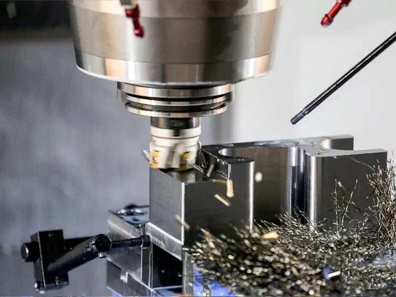
In the world of CNC machining, the difference between a pristine, aerospace-grade component and a piece of scrap metal often comes down to two critical variables: Cutting Speed and Feed Rate. For product designers and engineers, understanding the physics behind these parameters is not just about manufacturing theory—it is about ensuring your parts meet tight tolerances, achieve the desired surface finish, and remain cost-effective. At AFI Industrial Co., Ltd., we don’t just push buttons; we calculate the optimal “sweet spot” for every material and geometry. Here is a technical deep dive into how speed and feed rates directly influence the quality of your machined parts.
Table of Contents
Why Feeds and Speeds Matter in CNC Machining

In CNC machining, selecting the appropriate feed rate and spindle speed is crucial. It helps you produce high-quality parts and prevents premature tool wear. Each material has its specific feed rate and spindle speed. For example, machining aluminum requires a faster feed rate than machining titanium. Good machining results depend on how you set the feed rate and spindle speed.
Impact on Machining Quality
Changing speed and feed affects important machining results. Look at the table below to see what happens:
| Machining Outcome | Description |
|---|---|
| Material Removal Rate (MRR) | Higher feed rates remove more material faster. Too much can wear out tools. |
| Surface Finish | Fast feed rates make rough surfaces. Slow rates make smoother finishes. |
| Tool Life | Good feed rates help tools last longer. They stop tool edges from wearing out. |
| Cutting Efficiency | Fast spindle speeds cut quickly but can cause heat. Slow speeds make less heat, but cut slower. |
| Tool Wear | Spindle speed changes tool wear. Too fast wears tools out early. Too slow is not efficient. |
You must match the speed and feed to the material you’re cutting. Wrong settings can hurt accuracy and surface quality. High spindle speeds generate too much heat. This can cause parts to expand or warp. Tools can bend or get soft. Your part may not fit right.
Benefits of Optimization
When you set the speed and feed correctly, your shop reaps big benefits. Manufacturers say:

You can get:
- Up to 23% more parts made.
- 35% less machine downtime.
- 28% lower tooling costs.
- 42% better surface finish accuracy.
- 99.8% first-time-right production rate.
- Up to 40% longer machine life.
You also use less energy and make less scrap. These gains mean less rework. You spend more time making good parts for customers.
Issues from Incorrect Settings
Wrong speed and feed settings cause problems:
- Using settings for other materials makes heat, chips stick, and surfaces look bad.
- Using CAM software defaults can make cycles too long and cause rubbing.
- Not checking the tool diameter for chip load causes rubbing, heat, and rough finishes.
- Wrong tool coating makes more friction and can weld material to the tool.
- Skipping tool checks after runs means you miss wear and lose finish quality.
Tip: Always check your speed and feed for each job. Regular tool checks help you find problems early before they hurt your parts.
When you know how feeds and speeds work, you control your CNC machining results. You get better performance, save money, and make parts that meet high standards.
Understanding Feeds and Speeds
What Is Feed Rate?
Definition and Units
Feed Rate is the linear velocity at which the tool advances through the material.
In CNC machining, you see this value in the G-code as the letter F. You measure feed rate in inches per minute (IPM) or millimeters per minute (mm/min). The unit depends on whether your machine uses the imperial or metric system.
How Feed Rate Works
Feed rate tells your machine how quickly to push the tool through the material. You can calculate the feed rate using this formula:
- Feed Rate (IPM) = RPM × Number of Flutes × Chip Load
When you set the right feed rate, you help your tool cut efficiently. If you go too fast, you risk tool breakage and rough surfaces. If you go too slow, you waste time and may cause rubbing instead of cutting. You want to find the balance that matches your tool, material, and job.
What Is Cutting Speed?
Definition and Units
Cutting speed refers to the speed at which the cutting tool’s edge moves across the surface of the material. This value is important because it affects the quality of your cut, how long your tool lasts, and how much energy your machine uses. You usually measure cutting speed in surface feet per minute (SFM) or meters per minute (MPM).
How Cutting Speed Works
- SFM shows the linear speed at the tool’s cutting edge.
- RPM tells you how fast the tool spins, but this value changes with tool diameter to keep SFM constant.
- To convert SFM to RPM, use this formula:
RPM = (SFM × 12) / (π × Tool Diameter in inches)
You adjust the cutting speed
to match the material and tool. For example, aluminum needs a higher cutting speed than steel. If you set the speed too high, you may overheat the tool. If you set it too low, you reduce efficiency.
Feed Rate vs. Cutting Speed
Feed rate and cutting speed are not the same, but both matter for your machining results. Think of it like driving a car. Cutting Speed is how fast your tires are spinning(RPM), while Feed Rate is how fast the car is actually moving down the road(MPH).
To calculate the Spindle Speed(N) in RPM, machinists use the formula:
N = (V x 1000) / (π x D)
Where V is the cutting speed, and D is the tool diameter.
- Feed rate is how fast the tool moves into the workpiece. It affects how rough or smooth the surface will be and how quickly you finish the job.
- Cutting speed is how fast the tool’s edge moves against the material. It influences chip formation and how well your tool performs.
Note: You must balance both feed rate and cutting speed. When you set both correctly, you extend tool life, improve surface finish, and boost your shop’s efficiency.
When you understand feeds and speeds, you gain more control over your CNC machining. You make better choices, reduce waste, and deliver high-quality parts every time.
Key Factors Affecting Feeds and Speeds in Machining

Material Type and Hardness
The material you use changes your speed and feed choices. Each material, like aluminum or steel, is different. Harder materials need slower speeds and lighter feeds. This helps stop tool damage. Softer materials let you use faster speeds and heavier feeds. This makes work go faster.
You can use a hardness adjustment factor to help set your speed and feed. If your material has high Brinell hardness, you must lower your cutting speed. This keeps your tool from wearing out too fast. It also helps you get a better surface finish.
Here is a quick look at how different things change your machining results:
| Variable | Influence on Surface Roughness |
|---|---|
| Cutting Speed | Higher speeds make smoother surfaces |
| Feed per Tooth | Changes how smooth the surface is |
| Helix Angle | Changes cutting force and finish |
Note: Always check how hard your material is before you set speed and feed. This helps you get good results and makes your tool last longer.
Tool Material and Geometry
The tool you pick changes your speed and feed settings. You need to match the tool material to the workpiece. Carbide tools can go faster than high-speed steel tools. Ceramic and CBN tools work for hard materials but need careful speed control.
The shape of your tool matters too. The number of flutes, helix angle, and tip shape change how the tool cuts. More flutes can cut faster, but may clog in soft materials. The helix angle helps remove chips and affects the finish.
Here are some things to think about:
- The tool and workpiece must match for good cutting.
- The shape and design of the tool change how well it cuts and the finish.
- Special tool coatings lower friction and help tools last longer. They let you use higher speeds.
- Tool size is important. Small tools need slower speeds so they do not break.
Tip: Use coated tools for hard jobs. They last longer and let you use faster speed and feed.
Machine Capabilities
Your machine sets the limits for speed and feed. Modern CNC machines from AFI Industrial Co., Ltd can use many materials and tools. You still need to match your settings to the machine’s power and stability.
- Your setup must be stable. If your workpiece or tool is loose, slow down your speed and feed. This stops vibration.
- The length of your tool’s sticks out changes stability. Longer tools need a slower speed and feed to stop chatter.
- The machine’s top spindle speed and horsepower also set your limits. Always check these numbers before you start.
Remember: A stable setup lets you use faster speed and feed. This helps you work faster and make better parts.
When you think about material, tool, and machine together, you make better choices for feeds and speeds. This helps you get the best from your CNC machine and make high-quality parts every time.
Operation Type (Milling, Turning, Drilling)
You must adjust feeds and speeds based on the type of machining operation. Milling, turning, and drilling each have unique requirements. If you use the same settings for every operation, you risk tool damage and poor part quality. At AFI Industrial Co., Ltd, you benefit from machines and tools designed for all these operations. You need to match your parameters to the job for the best results.
Here is a quick comparison of how the operation type affects your choices:
| Operation Type | Speed Considerations | Feed Rate Considerations | Additional Factors |
|---|---|---|---|
| Turning | Set surface speed based on part rotation. Use faster speeds for soft materials, slower for hard alloys. | Control how fast the tool moves along the surface. Use deeper cuts for roughing, lighter for finishing. | Lubricants and coolants help reduce heat and prevent chip buildup. |
| Milling | Choose speed based on cutter diameter and number of flutes. Step-over distance changes the cycle time. | Adjust feed for cutter design. Multi-point cutters allow higher feed rates. | Careful setup prevents chatter and tool breakage. |
| Drilling | Set speed by drill diameter and material. Large drills need slower speeds. | Feed rate depends on drill size and material hardness. | Use coolant to clear chips and keep the drill cool. |
You see that each operation needs a different approach. For turning, you focus on the part’s rotation and tool path. For milling, you watch the cutter’s size and how many flutes it has. Drilling needs careful control of both speed and feed to avoid overheating and tool breakage. Always check your machine’s limits and the tool’s design before you start.
Tip: When you switch between milling, turning, and drilling, always review your feeds and speeds. This helps you avoid mistakes and keeps your tools in good shape.
Coolant and Lubrication
Coolant and lubrication play a big role in safe and effective machining. You cannot ignore them when setting feeds and speeds. They help you control heat, reduce friction, and protect both your tool and your workpiece.
| Factor | Description |
|---|---|
| Cutting Speed | Higher speeds make more heat. Coolant helps keep the tool and part cool, improving tool life. |
| Feed Rate | Faster feed rates remove more material but also make more heat. Coolant reduces friction and wear. |
| Depth of Cut | Deeper cuts focus heat in one spot. Coolant spreads out the heat and keeps the tool safe. |
- Coolant keeps the temperature down. This stops your tool and part from getting too hot and losing strength.
- Lubrication lowers friction. This helps your tool last longer and gives you a better surface finish.
- Good coolant and lubrication help you hold tight tolerances and make parts that fit right.
You need to pick the right coolant and use it the right way. If you skip this step, you risk tool failure, rough surfaces, and even machine damage. Always check your coolant system before you start a job.
Note: Using coolant and lubrication the right way lets you run faster speeds and feeds without hurting your tools or your parts.
Calculating Feeds and Speeds for CNC Machining

You need to know how to calculate feeds and speeds to get the best results from your CNC machining. When you use the right formulas, you set up your jobs for success. This section gives you the tools to find the optimal feed rate and optimal cutting speed for your work. You will see how to use these formulas and follow step-by-step examples for milling, turning, and drilling.
Essential Formulas
To set up your machine, you must use a few key formulas. These help you find the right spindle speed (RPM) and feed rate (IPM). You can use these formulas for most CNC operations.
| Parameter | Formula |
|---|---|
| RPM | RPM = (SFM ÷ Tool Diameter) × 3.82 |
| Feed Rate (IPM) | IPM = RPM × Number of Flutes × Chip Load |
- RPM tells you how fast your spindle should turn.
- Feed Rate (IPM) tells you how fast the tool moves through the material.
Note: SFM stands for surface feet per minute. Chip load is the thickness of material each tooth removes per revolution.
Feed Rate Formula
You use the feed rate formula to set how quickly your tool moves through the workpiece. The formula is:
Feed Rate (IPM) = RPM × Number of Flutes × Chip Load
You need to know your spindle speed (RPM), the number of flutes on your tool, and the chip load recommended for your tool and material. This formula helps you avoid tool breakage and get a smooth finish.
Cutting Speed Formula
Cutting speed is the speed at which the cutting edge moves across the material. You use this formula to find the right spindle speed:
RPM = (SFM ÷ Tool Diameter) × 3.82
You choose the SFM based on your material and tool type. Tool diameter is the width of your cutting tool. When you set the correct cutting speed, you protect your tool and improve your part quality.
Step-by-Step Calculation Examples
You can use these formulas for different machining operations. Here are step-by-step examples for milling, turning, and drilling. These examples use numbers that match the types of jobs you might run on AFI Industrial Co., Ltd’s machines.
Milling Example
Suppose you want to mill a slot in aluminum using a 0.5-inch, 4-flute carbide end mill. The recommended SFM for aluminum is 400, and the chip load is 0.002 inches.
- Calculate RPM:
- RPM = (400 ÷ 0.5) × 3.82 = 800 × 3.82 = 3,056 RPM
- Calculate Feed Rate:
- Feed Rate = 3,056 × 4 × 0.002 = 24.45 IPM
So, you set your spindle speed to 3,056 RPM and your feed rate to about 24 IPM.
Turning Example
You need to turn a steel shaft that is 100 mm long using a single-point tool. The recommended feed per revolution is 0.2 mm, and the spindle speed is 800 RPM.
- Calculate Machining Time:
- T = L / (f × N)
- T = 100 / (0.2 × 800) = 100 / 160 = 0.625 minutes (about 37.5 seconds)
You will finish the cut in about 38 seconds.
Drilling Example
You want to drill a 30 mm deep hole in brass using a 10 mm drill. The recommended feed per revolution is 0.1 mm, and the spindle speed is 1,000 RPM.
- Calculate Drilling Time:
- T = D / (f × N)
- T = 30 / (0.1 × 1,000) = 30 / 100 = 0.3 minutes (about 18 seconds)
You will complete the hole in about 18 seconds.
| Operation | Basic Formula | Example Calculation |
|---|---|---|
| Turning | T = L / (f × N) | T = 100 / (0.2 × 800) = 0.625 min (37.5 seconds) |
| Milling | T = L / F | T = 300 / 600 = 0.5 min (30 seconds) |
| Drilling | T = D / (f × N) | T = 30 / (0.1 × 1000) = 0.3 min (18 seconds) |
Tip: Always double-check your numbers before you start the machine. Small mistakes in your calculations can lead to tool breakage or poor part quality.
You can use these formulas and examples to set up your next job. When you calculate feeds and speeds, you get more control over your results. You make your tools last longer, your parts look better, and your shop runs more efficiently. With practice, you will find the best settings for every material and operation in your cnc machining work.
Recommended Feeds and Speeds by Material
Choosing the right feeds and speeds for each material is essential for quality CNC machining. You need to adjust your settings based on what you are cutting. This section gives you a quick reference for common materials you will see in AFI Industrial Co., Ltd’s machining services. Actual settings may change depending on your machine, tool, and job, but these values give you a strong starting point.
Steel
Steel is a common material in many shops. You must use slower speeds and lighter feeds compared to softer metals. This helps you avoid tool wear and keeps your surface finish smooth. For most steels, carbide tools work best. You should always check your tool manufacturer’s recommendations, but here are typical values:
| Steel Type | Cutting Speed (SFM) | Feed Rate (mm/tooth) | Feed Rate (in/tooth) |
|---|---|---|---|
| Mild Steel | 100 – 300 | 0.05 – 0.15 | 0.002 – 0.006 |
| Alloy Steel | 80 – 200 | 0.04 – 0.12 | 0.0015 – 0.005 |
| Tool Steel | 60 – 120 | 0.03 – 0.10 | 0.001 – 0.004 |
| 304 Stainless Steel | 60 – 120 | 0.05 | 0.002 |
Tip: When you machine harder steels, lower your cutting speed and use a lighter feed. This keeps your tool from wearing out too fast.
Aluminum
Aluminum is much softer than steel. You can use higher speeds and heavier feeds. This lets you remove material quickly and get a good finish. Carbide tools are a great choice for aluminum. Make sure to clear chips often to prevent clogging.
| Operation Type | Cutting Speed (SFM) | Feed Rate (IPR) | Feed per Tooth (mm) |
|---|---|---|---|
| Roughing | 1000 – 1500 | 0.008 – 0.012 | 0.1 – 0.25 |
| Finishing | 1500 – 2000 | 0.004 – 0.008 | 0.05 – 0.15 |
| Slotting | 800 – 1200 | 0.006 – 0.010 | 0.08 – 0.15 |
| Drilling | 300 – 500 | 0.006 – 0.010 | 0.1 – 0.3 |
- Spindle speed for aluminum often ranges from 1000 to 3000 RPM.
- Depth of cut can be 0.2 to 3 mm, depending on your setup.
Note: Always use coolant or air blast when machining aluminum. This helps you avoid chip welding and keeps your finish bright.
Stainless Steel
Stainless steel is tough and can work-harden quickly. You need to use slower speeds and moderate feeds. This helps you avoid tool breakage and keeps your part within tolerance. Use sharp, coated carbide tools for best results.
| Stainless Steel Type | Cutting Speed (SFM) | Feed Rate (mm/tooth) | Feed Rate (in/tooth) |
|---|---|---|---|
| 304 Stainless Steel | 60 – 120 | 0.05 | 0.002 |
| 316 Stainless Steel | 60 – 120 | 0.04 – 0.08 | 0.0015 – 0.003 |
| General Stainless | 150 – 250 | 0.045 – 0.06 | 0.0018 – 0.0024 |
Tip: Use plenty of coolant when cutting stainless steel. This helps you control heat and prevents work hardening.
You can use these tables as a starting point for your next job. Always adjust your feeds and speeds based on your machine, tool, and the exact material you are cutting. When you set the right parameters, you get better tool life, smoother finishes, and more reliable results.
Brass
Brass is a popular choice for CNC machining because it is easy to cut and produces a smooth finish. When you machine brass, you can use higher speeds and moderate feeds compared to harder metals. This helps you achieve precise results and extend tool life. You should always check your tool manufacturer’s guidelines, but the following recommendations give you a reliable starting point for most brass machining jobs:
- Cutting speed: 200–300 surface feet per minute (sfm) works well for most brass alloys.
- Cutter feed rate: 0.002–0.005 inches per tooth is ideal for fine work.
- General feed rates: 0.001–0.010 inches per tooth cover a wide range of brass machining needs.
Tip: Brass does not work harden as quickly as stainless steel or steel. You can use sharper tools and higher speeds to get a clean, bright finish. Always clear chips often to avoid scratching the surface.
If you want to maximize your results, keep your tools sharp and use a light coolant or air blast to remove chips. This helps you avoid built-up edge and keeps your part looking professional.
Plastics
Plastics require a different approach than metals. You need to use lower spindle speeds and lighter feeds to prevent melting or chipping. The right settings depend on the type and thickness of the plastic. Here is a quick reference table for common plastics machining:
| Parameter | Value |
|---|---|
| Spindle Speed | 800–1000 RPM |
| Feed Rate | 0.1–0.2 mm/rev |
| Cutting Depth | 0.2–0.5 mm |
You can adjust these values based on the thickness of your material:
- For thin plastics (1–3 mm), use a feed rate of 0.10–0.15 mm/rev for precision parts.
- For medium thickness (3–6 mm), set the feed rate to 0.15–0.18 mm/rev for general machining.
- For thick plastics (over 6 mm), increase the feed rate to 0.18–0.20 mm/rev for heavy-duty parts.
Note: Plastics can melt or deform if you use too much heat. Always use sharp tools and consider air cooling to keep the temperature down. Avoid deep cuts in a single pass to prevent warping.
When you follow these guidelines, you get clean edges and accurate parts. Adjust your feeds and speeds as needed for each job to match the specific plastic and part design.
Feeds and Speeds Table for CNC Machining
Quick Reference Table
You need a quick way to check the right feeds and speeds for your CNC jobs. This table gives you a fast reference for the most common materials and operations. You can use it to set up your machine for milling, turning, or drilling. The values below help you get started, but always adjust for your specific tool, machine, and job.
| Material | Operation | Cutting Speed (SFM) | Feed per Tooth (in) | Typical RPM (1/2″ Tool) | Notes |
|---|---|---|---|---|---|
| Mild Steel | Milling | 100 – 300 | 0.002 – 0.006 | 800 – 1800 | Use coolant for the best finish |
| Turning | 80 – 200 | 0.004 – 0.012 | 600 – 1600 | Reduce speed for hard steel | |
| Drilling | 60 – 120 | 0.002 – 0.008 | 500 – 1200 | Peck drill for deep holes | |
| Aluminum | Milling | 800 – 1500 | 0.005 – 0.015 | 3000 – 6000 | Clear chips often |
| Turning | 600 – 1200 | 0.004 – 0.012 | 2500 – 5000 | Use sharp carbide tools | |
| Drilling | 300 – 500 | 0.004 – 0.012 | 1200 – 2000 | Use an air blast or coolant | |
| Stainless Steel | Milling | 60 – 120 | 0.0015 – 0.004 | 500 – 1200 | Use coated carbide tools |
| Turning | 60 – 120 | 0.002 – 0.006 | 500 – 1200 | Avoid work hardening | |
| Drilling | 40 – 80 | 0.001 – 0.004 | 300 – 800 | Use plenty of coolant | |
| Brass | Milling | 200 – 400 | 0.003 – 0.010 | 1500 – 3000 | Chips clear easily |
| Turning | 200 – 400 | 0.003 – 0.010 | 1500 – 3000 | Use light feed for fine work | |
| Drilling | 100 – 200 | 0.002 – 0.008 | 800 – 1500 | Avoid tool dwell | |
| Plastics | Milling | 200 – 600 | 0.002 – 0.008 | 1000 – 2500 | Prevent melting, use air |
| Turning | 200 – 600 | 0.002 – 0.008 | 1000 – 2500 | Use sharp tools, light cuts | |
| Drilling | 100 – 300 | 0.002 – 0.008 | 800 – 2000 | Slow feed, avoid heat |
Tip: Start with the lower end of the range if you are new to CNC or using a small machine. Increase speed and feed as you gain confidence and see stable results.
- SFM stands for Surface Feet per Minute.
- Feed per Tooth is how much each tooth of the cutter moves into the material per revolution.
- RPM is based on a 1/2″ (12.7 mm) tool. Adjust for other sizes using the formulas in the previous section.
You can print this table and keep it near your CNC machine. When you set up a new job, check the material and operation, then use these numbers to get started. If you hear chatter, see rough finishes, or notice tool wear, adjust your settings. You will get better results as you learn how your machine and tools respond.
Note: Always check your tool manufacturer’s recommendations for the best results. These values are starting points and may need fine-tuning for your specific setup.
Optimizing Feeds and Speeds for Machining Operations
When you want the best results from your CNC machining, you must match your speed and feed settings to each operation. Milling, turning, and drilling all need different approaches. At AFI Industrial Co., Ltd, you have access to advanced machines and a wide range of tools. You can get the most out of your equipment by understanding how to set feeds and speeds for each type of machining operation.
Milling
Key Considerations
You need to think about several factors when setting speed and feed for milling:
- Material types matter. Softer materials like aluminum let you use higher RPM, while harder metals like steel need moderate RPM.
- Tool selection is important. Carbide tools work well for high-speed jobs, especially if your setup is less rigid.
- Adaptive control helps. Some machines can adjust speed and feed automatically based on the load.
- Machine calibration keeps your cuts accurate. Regular checks prevent sluggish feed motion.
- Simulation is useful. Running a virtual cut can show you problems before you start.
- Toolpath optimization, such as trochoidal milling, keeps chip load steady and reduces heat.
- Energy efficiency improves when you optimize feed rates. You can save up to 40% on power.
- Monitoring conditions like vibration and temperature helps you avoid overload and get a better cut.
Tip: Always check your machine and tool before you start. A quick simulation can help you spot issues early.
Typical Values
| Material | Cutting Speed (SFM) | Feed per Tooth (in) | Typical RPM (1/2″ Tool) |
|---|---|---|---|
| Mild Steel | 100 – 300 | 0.002 – 0.006 | 800 – 1800 |
| Aluminum | 800 – 1500 | 0.005 – 0.015 | 3000 – 6000 |
| Stainless | 60 – 120 | 0.0015 – 0.004 | 500 – 1200 |
| Brass | 200 – 400 | 0.003 – 0.010 | 1500 – 3000 |
| Plastics | 200 – 600 | 0.002 – 0.008 | 1000 – 2500 |
Start with the lower end if you are new. Increase speed and feed as you gain confidence.
Turning
Key Considerations
You must set speed and feed for turning based on the part and tool. Use slower speeds for hard materials and faster speeds for soft ones. Carbide inserts let you use higher speeds. Always check your tool’s sharpness and the machine’s stability. If you see vibration or hear chatter, reduce your speed and feed. Use coolant to keep the tool and part cool.
Note: For roughing, use deeper cuts and higher feed. For finishing, use lighter cuts and slower feed for a smooth surface.
Typical Values
| Material | Cutting Speed (SFM) | Feed per Rev (in) | Typical RPM (1″ Dia) |
|---|---|---|---|
| Mild Steel | 80 – 200 | 0.004 – 0.012 | 300 – 800 |
| Aluminum | 600 – 1200 | 0.004 – 0.012 | 1000 – 2500 |
| Stainless | 60 – 120 | 0.002 – 0.006 | 200 – 600 |
| Brass | 200 – 400 | 0.003 – 0.010 | 800 – 1600 |
| Plastics | 200 – 600 | 0.002 – 0.008 | 800 – 2000 |
Drilling
Key Considerations
Drilling needs careful control of speed and feed. Large drills need slower speeds. Hard materials need slower speeds and lighter feeds. Use coolant to clear chips and keep the drill cool. Peck drilling helps remove chips from deep holes. Always use a sharp drill bit for the best results.
Tip: If you see smoke or hear squealing, slow down and check your drill bit.
Typical Values
| Material | Cutting Speed (SFM) | Feed per Rev (in) | Typical RPM (1/4″ Drill) |
|---|---|---|---|
| Mild Steel | 60 – 120 | 0.002 – 0.008 | 800 – 1200 |
| Aluminum | 300 – 500 | 0.004 – 0.012 | 2000 – 3000 |
| Stainless | 40 – 80 | 0.001 – 0.004 | 500 – 900 |
| Brass | 100 – 200 | 0.002 – 0.008 | 1200 – 2000 |
| Plastics | 100 – 300 | 0.002 – 0.008 | 1200 – 2000 |
By matching your speed and feed to the operation and material, you get the most from your machining operations. You protect your tools, improve your finish, and make your shop more efficient. Always review your settings before you start. This approach helps you achieve the optimal feed rate and the best results in every job.
How Feeds and Speeds Affect Machining Performance
When you set feeds and speeds correctly, you control the outcome of your CNC machining. These settings have a direct impact on tool wear, part quality, and productivity. At AFI Industrial Co., Ltd, you see the results in high-quality surface finishes and efficient operations. Let’s look at how feeds and speeds shape your machining performance.
Tool Life
You want your tools to last as long as possible. The right feeds and speeds help you avoid tool damage and keep your shop running smoothly. Here’s how your choices affect tool life:
- Moderate cutting speeds help control tool wear. They keep thermal conditions stable and allow chips to clear away.
- Very high cutting speeds can generate too much heat. This heat causes the tool material to break down or oxidize.
- Higher feed rates increase friction and stress on the tool. This can lead to abrasive wear or even chipping.
- If you balance speed and feed, you get optimal performance and longer tool life.
Tip: Watch for signs of wear on your tools. If you see chips or dull edges, check your speed and feed settings. Adjusting them can prevent early tool failure.
Surface Finish
Surface finish matters for every part you make. It affects how parts fit, move, and resist corrosion. You control surface finish by setting the right feeds and speeds.
- Feed rate changes how much material you remove and how much heat you generate.
- The right feed rate gives you a smooth surface and reduces the need for extra finishing.
- Managing feed rate also helps your tool last longer and keeps the surface quality high.
When you optimize cutting parameters, you get a better surface finish. This means your parts work better and last longer. At AFI Industrial Co., Ltd, you see this in every project. High-quality finishes are a sign of good process control.
Machining Efficiency
You want your shop to run fast and make good parts. Feeds and speeds play a big role in machining efficiency.
- The feed rate affects tool life, surface finish, and how quickly you finish a job.
- Higher feed rates remove material faster and boost productivity, but they can wear out tools sooner.
- Lower feed rates improve surface finish and tool life, but they slow down your cycle times.
Finding the right balance helps you get the most from your machine. You make more parts in less time and keep your quality high. When you set feeds and speeds for optimal performance, you improve every part of your process.
Note: Always review your settings before you start a job. Small changes in speed or feed can make a big difference in tool life, finish, and efficiency.
By understanding how feeds and speeds affect tool life, surface finish, and machining efficiency, you take control of your results. You avoid tool damage, deliver better performance, and keep your shop running at its best.
Step-by-Step Guide to Feeds and Speeds Optimization
Assess Your Setup
Start by looking at your CNC setup before you change any feeds or speeds. Check your machine’s condition. Make sure the spindle runs smoothly, and the tool holders are tight. Look at your workholding. The part must stay secure during machining operations. If you see any vibration or movement, fix it before you continue.
Review your tool length and how far it sticks out. A long tool can cause chatter and poor surface finish. Use the shortest tool possible for your job. Check your coolant system. Make sure it works and delivers coolant to the cutting zone. A working coolant system helps you control heat and improve tool life.
Tip: Take a few minutes to inspect your setup before every job. This habit helps you avoid mistakes and keeps your process stable.
Gather Material and Tool Data
Next, collect all the information about your material and cutting tool. Write down the material type, such as aluminum, mild steel, or plastic. Find out the hardness if you can. Harder materials need slower speeds and lighter feeds. Softer materials let you use faster settings.
Record the tool material and geometry. Note the number of flutes, the tool diameter, and the type of coating. Each detail affects your settings. For example, carbide tools allow higher speeds than high-speed steel. A coated tool can handle more heat and friction.
You also need to know the tool’s recommended chip load. This value tells you how much material each tooth should remove. You can find this in the tool’s technical sheet or catalog. Write down all these details. You will use them to calculate the optimal feed rate for your job.
Note: Missing or wrong data leads to poor performance and tool breakage. Always double-check your numbers.
Use Manufacturer Recommendations
Now, look up the recommended feeds and speeds from your tool and material suppliers. Most manufacturers provide charts or tables with starting values. These recommendations are based on tests and real-world experience. They give you a safe starting point for your machining operations.
Find the recommended cutting speed (SFM or MPM) and chip load for your tool and material. Use these values to set your initial spindle speed and feed rate. If you use a coated tool or a special geometry, check if the manufacturer suggests different values.
Tip: Do not guess or use default settings from your CAM software. Manufacturer recommendations help you avoid common mistakes and get better results from the start.
If you follow these steps, you set a strong foundation for optimizing feeds and speeds. You reduce the risk of tool failure and improve your part quality. You also make it easier to adjust and fine-tune your process as you move forward.
Apply Formulas and Tables
You need to use the right formulas and tables to set your feeds and speeds. This step is where you turn your data into real numbers for your CNC machine. Start by gathering your tool diameter, number of flutes, chip load, and the recommended cutting speed for your material. These values come from your tool manufacturer or a trusted reference chart.
You can use these two main formulas:
- **Spindle Speed (RPM):**
  RPM = (Cutting Speed × 12) / (π × Tool Diameter in inches)

- **Feed Rate (IPM):**
  Feed Rate = RPM × Number of Flutes × Chip Load
Tables make this process easier. You look up the recommended cutting speed and chip load for your material and tool. For example, if you are cutting aluminum with a 0.5-inch carbide end mill, you might see a cutting speed of 400 SFM and a chip load of 0.002 inches per tooth.
| Material | Tool Type | Cutting Speed (SFM) | Chip Load (in/tooth) |
|---|---|---|---|
| Aluminum | Carbide | 400 | 0.002 |
| Mild Steel | Carbide | 200 | 0.0015 |
| Brass | Carbide | 300 | 0.0025 |
Plug these numbers into your formulas. For a 0.5-inch tool cutting aluminum:
- RPM = (400 × 12) / (3.14 × 0.5) ≈ 3,056
- Feed Rate = 3,056 × 4 flutes × 0.002 = 24.45 IPM
Tip: Always double-check your math. Inaccurate calculations can cause tool breakage, wasted material, and poor surface finish. Precision matters.
Common mistakes can happen at this stage. You might use the wrong chip load, forget to adjust for tool diameter, or skip checking the table for your specific tool. These errors can lead to rough finishes and unnecessary tool wear. To avoid them:
- Always refer to tooling guidelines for recommended speeds and feeds.
- Use the correct formula for your operation.
- Double-check your numbers before you start the machine.
If you are unsure, run a test cut on scrap material. This lets you fine-tune your settings before you start full production. For large jobs, consider using a monitoring system to track your machine’s performance in real time.
Note: The balance between speed and feed is critical. Too fast a spindle speed with too slow a feed rate can create friction heat that melts the material. Always aim for a balance that matches your tool, material, and machine.
By applying formulas and tables carefully, you set yourself up for success. You get better results, protect your tools, and make parts that meet your standards.
Troubleshooting Feeds and Speeds Issues

When you run CNC machines, you may face problems with feeds and speeds. Recognizing these issues early helps you avoid tool damage and keeps your shop running smoothly. At AFI Industrial Co., Ltd, you benefit from proven quality control methods that prevent defects and improve your results.
Signs of Incorrect Settings
You can spot trouble with feeds and speeds by watching for these warning signs:
- Tools wear out faster than expected.
- The machine makes loud noises or vibrates.
- The surface finish looks rough or uneven.
- Chips are too small, too large, or stick to the tool.
- The machine stalls or the spindle slows down.
- Parts come out with the wrong size or shape.
Tip: If you see blue chips or smoke, your settings may be too aggressive. If you hear squealing, your feed rate may be too low.
Diagnostic Steps
You can use a simple checklist to find the cause of your machining issues:
- Check your tool for wear or chipping.
- Review your feed rate and cutting speed settings.
- Inspect the workpiece for signs of burning or poor finish.
- Listen for changes in machine sound or vibration.
- Look at the chips. Are they the right size and color?
- Confirm that coolant or lubrication is reaching the cutting zone.
- Make sure the tool is installed correctly and not sticking out too far.
| Symptom | Possible Cause | What to Check |
|---|---|---|
| The tool wears quickly | Speed too high, feed too low | Tool material, settings |
| Poor surface finish | Feed too high, dull tool | Tool sharpness, chip load |
| Machine vibration | Tool overhang, loose setup | Tool length, workholding |
| Chips stick to the tool | Not enough coolant, wrong speed | Coolant flow, speed |
Solutions and Adjustments
You can fix most feed and speed problems with a few simple changes:
- Lower the spindle speed if you see tool wear or burning.
- Increase the feed rate if you hear squealing or see rubbing marks.
- Use the shortest tool possible to reduce vibration.
- Adjust coolant flow to keep the tool and part cool.
- Switch to a coated tool for tough materials.
- Double-check your formulas and tables for the correct settings.
- Run a test cut on scrap material before starting a big job.
Note: Small changes in speed or feed can make a big difference in tool life and part quality. Always monitor your results and adjust as needed.
When you follow these steps, you improve your machining performance and reduce downtime. You also prevent tool damage and make sure every part meets your standards. AFI Industrial Co., Ltd’s focus on quality control helps you catch problems early and keep your shop running at its best.
Optimizing feeds and speeds gives you better CNC machining results. You now have practical formulas, tables, and step-by-step guidance to help you set up your jobs. Apply these tips in your shop and watch your part quality improve. Track your results and adjust your settings as you learn. Remember, ongoing learning and small changes lead to big gains in tool life, finish, and productivity.
To obtain higher-quality machined products or to discuss more machining techniques with our engineers, please contact us.
FAQ
You risk tool breakage, poor surface finish, and wasted material. You may also see more heat, vibration, and part inaccuracy. Always check your settings before you start a job.
You see smooth chips, a clean surface, and steady machine sounds. Your tool lasts longer. If you notice burning, chatter, or rough finishes, adjust your settings.
No. Each material needs its own settings. Steel, aluminum, and plastics all require different speeds and feeds. Always check the recommended values for your specific material.
Larger tools need slower spindle speeds to keep the cutting edge moving at the right speed. Use the formula:RPM = (Cutting Speed × 12) / (π × Tool Diameter in inches)
Chip load is the thickness of material each tooth removes per revolution. It affects tool life and surface finish. Too high a chip load can break your tool. Too low can cause rubbing.
Coolant helps control heat, improves tool life, and gives a better finish. For most metals, use a coolant. For some plastics or dry machining, an air blast may work better.
Check before every new job or when you change materials, tools, or operations. Regular checks help you avoid mistakes and keep your parts within tolerance.
