Engineers at custom metal parts manufacturer AFI Parts manage residual stress during CNC machining operations. Controlling internal stress maintains dimensional accuracy within a 0.005 mm tolerance over a 10,000-hour operational lifecycle. Stress mitigation minimizes dimensional deviation and maximizes component fatigue life. Components exceeding baseline fatigue parameters eliminate warranty claims and satisfy client specifications.
Applying targeted stress-relief techniques prevents structural deformation and microcracking. These methodologies also decrease surface roughness values (Ra) to below 0.8 micrometers. Mastering these metallurgical principles enables AFI parts to execute contracts in highly regulated aerospace and medical device sectors.
Key Takeaways
- AFI parts engineers analyze residual stress characteristics in aerospace and automotive metal components.
- Residual stress alters component tensile strength, volumetric accuracy, and operational reliability. Executing stress mitigation protocols during the pre-machining phase extends component fatigue life and eliminates post-delivery warranty returns. Meeting tight tolerance specifications fulfills the client’s requirements.
- Thermal annealing and vibration stress relief operations eliminate structural bending and surface cracking.
- Sourcing application-specific raw materials determines the success of stress management.
- Materials possessing homogeneous microstructures and low thermal expansion coefficients (α < 12 × 10-6 / ℃) restrict residual stress accumulation. Modifying active machining parameters, specifically feed rate (mm/rev) and spindle speed (RPM), significantly reduces surface tensile stress.
- Programming optimized tool paths distributes thermal energy and mechanical cutting forces uniformly across the workpiece surface. Uniform force distribution prevents localized stress concentration zones.
- Executing post-machining operations, including solution heat treatment and media shot peening, increases component tensile strength and geometric stability.
- Implementing stringent quality control protocols quantifies and tracks internal residual stress profiles. Data-driven inspection guarantees components meet ISO 9001 quality specifications.
Table of Contents
Residual Stress in CNC Machining Overview
What Is Residual Stress?
Residual stress constitutes internal mechanical forces residing within metal components following CNC machining operations. These internal forces maintain equilibrium without the application of external mechanical loads. The stress tensor σij quantifies these internal forces, differentiating between tensile stress components and compressive stress components.
Residual stress occurs when material undergoes heterogeneous plastic deformation during the metal removal process. The combination of localized yield strength exceedance and rapid cooling cycles distorts the material lattice. These internal stress gradients alter component geometry, ultimate tensile strength, and operational kinematics.
How Residual Stress Forms
Residual stress accumulates through a combination of mechanical plastic deformation and thermal expansion cycles. Tool engagement generates surface friction and rapid heat accumulation. The exterior material boundaries reach temperatures exceeding 600°C and cool rapidly, while the internal core temperature remains ambient. This temperature differential generates internal stress gradients. The exact mechanism governing machining-induced residual stress involves multi-physics interactions.
The cutting zone acts as the epicenter for thermomechanical force application. Surface materials undergo permanent plastic deformation due to simultaneous heat application and cutting force shear.
During CNC machining cycles, the cutting tool displaces material volumes while transferring kinetic energy as heat. This action causes surface layers to undergo varying states of tension and compression. Upon tool disengagement, the surface layer attempts to contract thermally, but the cooler substrate restricts this physical movement. This physical restriction traps permanent stress within the material lattice.
Why It Matters for Custom Parts
Residual stress dictates the operational limits of components produced by custom metal parts manufacturers. Stress values dictate component fatigue limits and field reliability.
The table below quantifies the impact of controlling residual stress parameters:
| Aspect of Manufacturing | Explanation | Metric / Tolerance Impact |
|---|---|---|
| Dimensional Stability | Internal stress gradients warp components, altering geometric dimensions. | Deviation reduction from 0.05 mm to <0.005 mm. |
| Machining Accuracy | Unbalanced stress vectors introduce tool deflection. | Maintains CpK values above 1.33 during production. |
| Structural Integrity | Residual stress accelerates micro-crack propagation under load. | Fatigue life increases by up to 50,000 cycles. |
| Manufacturing Efficiency | Stable material structures increase throughput and eliminate rework. | Reduces setup times by 20% and scrap rates to <1%. |
Custom components require adherence to micrometer-level precision specifications. Neglecting residual stress management protocols results in structural failure or assembly misalignment.
Engineers implementing precise stress controls manufacture components that withstand extended operational lifecycles. Applying these principles eliminates material waste and redundant machining passes, increasing overall factory throughput.
Main Causes of Residual Stress
Material Properties
Material composition directly governs residual stress generation during CNC machining cycles. Distinct metal alloys exhibit specific reactions to heat application and mechanical shear forces. Materials like Aluminum 7075-T6 expand at a rate of 23.6㎛/m℃ while Titanium Ti-6Al-4V expands at 8.6㎛/m℃. These specific thermal coefficients dictate the magnitude of stress forming within the lattice.
Fast machining velocities induce steep thermal gradients across the workpiece cross-section. Heat energy causes localized lattice expansion, followed by immediate contraction upon coolant application. This cyclic dimension change locks permanent stress forces within the part.
Mechanical deformation transpires when the cutting tool geometry displaces the material matrix. The tool tip compresses the immediate surface layer while placing the subsurface region under tension. This non-uniform displacement generates alternating compressive and tensile stress layers. Temperatures exceeding the material transformation threshold trigger phase transformations within the microstructure. The formation of martensite or other new phases traps volumetric stress within the part.
Note: Engineers reduce residual stress accumulation by selecting application-specific alloys. Materials exhibiting homogeneous grain structures and low thermal expansion coefficients provide superior stability.
Machining Parameters
Operators adjust feed rate (fz), cutting speed (vc), and depth of cut (ap) to regulate residual stress in CNC machining. Modifying these specific numerical settings alters the tool-workpiece interaction dynamics.
Elevating feed rates increases the material engagement volume per revolution. This parameter adjustment increases plastic deformation rates but lowers compressive stress magnitude due to non-uniform material yielding. Depth of cut parameters influence stress generation, though they exert less impact than velocity or feed inputs. At depths exceeding 2.0 mm, heat dissipation paths alter the final stress distribution profile. Elevating cutting velocities to ranges between 200 m/min and 350 m/min generates higher compressive residual stress values.
High-velocity machining prioritizes mechanical shear deformation while minimizing the duration of heat transfer into the substrate. Programmers balance these numerical inputs to maintain stress thresholds below 50 MPa. Establishing calculated baseline parameters increases component yield rates and eliminates post-machining distortion.
Thermal Effects
Thermal expansion and contraction cycles constitute a primary source of residual stress in CNC machining. Friction generates heat loads exceeding 800°C at the tool-chip interface. The workpiece surface absorbs heat faster than the internal core material. During the cooling phase, the surface layer attempts volumetric shrinkage, but the core geometry resists this action. This mechanical resistance establishes permanent stress fields. Extreme heating and cooling rates force the surface to contract disproportionately compared to the substrate. Temperature differentials across the workpiece axis induce geometric warping and structural distortion. Failing to extract heat rapidly initiates micro-crack formation, degrading the component’s ultimate tensile strength.
Tip: Implementing high-pressure coolant delivery systems at 70 Bar and regulating spindle velocity mitigates thermal shock. Maintaining constant workpiece temperatures via flood cooling halts stress accumulation. Analyzing these variables allows AFI parts engineers to apply optimal stress management techniques during CNC machining. Quality assurance teams measure each thermal factor to ensure components meet aerospace tolerances.
Part Geometry
Workpiece geometry determines the distribution and magnitude of residual stress during CNC machining operations.
A component’s physical dimensions and cross-sectional profiles dictate its mechanical resistance and thermal dissipation capabilities. Block geometries and standard cylinders distribute forces evenly and exhibit lower stress concentrations. Multi-axis geometries containing 1.5 mm wall sections, internal radii under 0.5 mm, or cavities exceeding 50 mm in depth trap stress forces internally.
Note: Components featuring sections under 2.0 mm thickness or abrupt dimensional transitions possess a high probability of structural warping post-machining. Engineers execute design for manufacturability (DFM) reviews to mitigate these geometric risks.
Tool engagement pathways dictate stress generation.
End mills traversing a surface impart kinetic energy and shear forces. Heat and force distribution vary across differing geometric profiles. Variations in cooling rates across mass transitions trigger part distortion and dimensional drift.
Internal corners lacking radii function as mechanical stress concentrators.
Applied loads exceeding the material yield strength at these focal points initiate crack propagation.
Wall sections measuring under 2.0 mm lack thermal mass for heat dissipation.
Thermal accumulation induces geometric distortion or material fracture when engineers fail to implement stress controls. Uninterrupted planar surfaces exhibit warping when tool paths fail to distribute heat loads systematically. Blind cavities trap cutting fluid and heat energy, restricting uniform thermal stabilization.
Cutting velocity (vc), feed per tooth (fz), and tool rake angle dictate stress outcomes across varying geometries.
Limiting cutting velocities and employing positive rake angle tools decreases surface tensile stress limits. Maintaining these parameters prevents surface crack initiation. Uncontrolled processes allow stress forces to exceed material yield strength, causing parts to deviate from CAD geometry. Dimensional deviation causes part rejection when specifications demand tolerances of ±0.01 mm. Designers and CNC programmers collaborate to engineer tool paths accommodating specific geometries.
Engineering teams map high-risk stress accumulation zones before chip generation. Teams modify CAD files to replace sharp intersections with fillets or incorporate sacrificial support ribs for thin sections. CAM programmers structure tool engagement sequences to apply heat and mechanical force uniformly across the stock material.
Tip: Implementing finite element analysis (FEA) software maps predictive stress tensor distribution within the component. Data analysis permits engineers to adjust G-code parameters before physical machining. Managing Residual Stress in CNC Machining requires assessing multiple variables, and part geometry dictates the baseline strategy. Analyzing geometric mass distribution enables AFI parts to manufacture precision components, yielding extended operational lifecycles.
Material Selection & Preparation

Choosing Materials for Stress Control
Selecting specific metal alloys determines the baseline success of stress control protocols. Distinct atomic structures react according to material-specific yield strengths and thermal conductivities. Aluminum alloys, specifically 6061-T6, maintain lower residual stress profiles due to their face-centered cubic lattice stability. Austenitic stainless steels, such as 304L, accumulate substantial internal stress without proper parameter management. Titanium Ti-6Al-4V resists mechanical deformation but requires low-velocity machining to prevent rapid stress accumulation.
AFI parts engineers specify alloys possessing thermal expansion coefficients below 15㎛/m℃ and homogeneous microstructures. These material properties lock the component dimensions within the required tolerance bands post-machining. Engineers calculate specific cutting forces (kc) for each alloy. Non-uniform material blanks containing localized hardness variations trap stress gradients. Sourcing billets featuring consistent Rockwell hardness values (HRC) and uniform grain sizes guarantees superior manufacturing outcomes.
Tip: Engineers must extract material properties, including yield strength (Rp0.2) and thermal conductivity (λ), from the material datasheet before CAM programming. Data integration ensures that cutting parameters align with material physics.
Pre-Treatment Methods
Pre-treatment thermal cycles prepare raw billets for CNC machining operations. Implementing these procedures reduces pre-existing internal stress limits and locks the geometric shape.
The table below defines pre-treatment methodologies and their quantified effectiveness:
| Method | Description | Effectiveness |
|---|---|---|
| Annealing | Elevating the temperature to 400°C – 800°C, followed by controlled cooling to relieve internal stresses. | Reduces residual tensions by up to 85%. |
| Thermal Stabilization | Implementing steady-state heating to lock the dimensional geometry. | Increases dimensional stability tolerance by 40%. |
| Natural Aging | Maintaining the workpiece at ambient 20°C conditions to release stress over 100+ hours. | Lowers residual stress limits gradually. |
| Artificial Aging | Applying 150°C heat or cryogenic freezing to reduce micro-stress after quenching operations. | Prevents structural distortion and material breaking. |
| Vibration Stress Relief | Inducing 50-150 Hz sub-resonant mechanical vibrations to redistribute internal stress. | Decreases residual stress limits by 50%-70%. |
Stress-Relief Annealing
Stress-relief annealing serves as a standard thermal process to eliminate internal stress vectors. Operators elevate the metal temperature to approximately 50-100°C below the transformation phase and utilize controlled furnace cooling rates of 20°C per hour. Thermal energy allows lattice atoms to migrate to equilibrium positions, releasing trapped mechanical stress. Components subjected to annealing maintain structural tolerances of ±0.005 mm and exhibit zero cracking under load. AFI parts specify annealing for 4140 steel, 7075 aluminum, and C36000 copper alloys.
Note: Technicians execute annealing protocols before final finishing passes (where ap < 0.2mm). Annealing halts dimensional warping and reduces surface roughness (Ra) values.
Normalizing
Normalizing functions as an alternative heat treatment to control stress forces. Technicians heat the metal billet to 30-50°C above the upper critical temperature limit and execute ambient air cooling. This thermal cycle refines the grain structure and establishes a uniform hardness profile. Normalizing increases material tensile strength and eliminates bending forces during heavy material removal operations. Engineers mandate normalizing for 1045 carbon steel and 4340 alloy steel.
Callout: Implementing normalizing procedures decreases cutting forces (Fc) and minimizes the probability of residual stress generation in CNC machining. Executing pre-treatment protocols ensures components meet strict dimensional tolerances and operational specifications. AFI parts utilizes these steps to deliver components fulfilling AS9100 quality standards.
Machining Strategies for Stress Management

Optimizing Feeds and Speeds
Feed rate (fz) and cutting speed (vc) govern the physics of CNC machining. These parameters dictate tool velocity (m/min) and material removal per revolution (mm/rev). Inputting precise numerical values limits heat generation and mechanical force accumulation. Limiting energy transfer reduces internal stress generation within the material matrix.
Machinists calculate specific feed and speed values using formulaic calculations based on material hardness and component geometry. Exceeding standard cutting velocity limits accelerates flank wear on carbide cutting inserts. High-velocity parameters generate thermal loads exceeding 800°C, increasing residual stress forces. Utilizing feed rates below 0.05 mm/rev reduces cutting pressure but decreases the overall material removal rate (MRR), extending cycle times.
The table below quantifies how these parameters alter tool degradation, stress values, and corrosion resistance:
| Parameter | Influence on Tool Wear | Influence on Residual Stresses | Influence on Corrosion Resistance |
|---|---|---|---|
| Cutting Speed (vc) | High (Accelerates flank wear) | High (Increases thermal gradient) | Low |
| Feed Rate (fn) | Moderate | Low (Controls chip thickness) | High (Determines surface finish) |
Tip: Programmers initiate machining cycles using the minimum feeds and speeds specified by the tooling manufacturer. Operators execute 5% incremental adjustments and utilize coordinate measuring machines (CMM) to check for deflection. Regulating these variables maintains workpiece temperature below 40°C and locks dimensional stability. Parameter optimization ensures fluid chip evacuation and precise process control.
Tool Path Planning
Tool path planning defines the exact 3D coordinates the cutting tool traverses. Strategic coordinate planning distributes thermal loads and mechanical forces. Distributing energy lowers the total stress limits within the component.
CAM programmers apply specific algorithms to achieve optimal surface finish. Symmetrical milling operations remove identical material volumes from opposing workpiece faces simultaneously. This synchronous material removal balances opposing stress vectors.
Adaptive clearing tool paths utilize trochoidal motions to maintain a constant tool engagement angle and distribute cutting forces. Constant engagement prevents localized heat accumulation. Path planning requires the elimination of 90-degree directional changes or rapid vector reversals. Executing spline-based smooth transitions stabilizes tool pressure. Stabilizing pressure eliminates component bending and edge fracture.
Note: CAM simulation software calculates predictive stress accumulation zones. Programmers modify the generated G-code to redistribute tool loads prior to physical machining. Strategic tool path planning yields components exhibiting superior fitment and extended lifecycle durability.
Coolant and Temperature Control
Coolant application and temperature monitoring define the success of managing stress in CNC machining. High-pressure coolant delivery systems maintain cutting zone temperatures and flush metal chips from the interface. Immediate heat extraction prevents the workpiece from surpassing its thermal expansion limits, halting stress formation.
The table below defines cooling methods and their effect on stress variables:
| Evidence Description | Effect on Residual Stress |
|---|---|
| Cryogenic cooling (Liquid Nitrogen) reduces cutting temperatures to -196°C. | Minimizes formation of tensile residual stresses by 80%. |
| Thermal lThermal loads cause formation of tensile stresses. | Microstructural phase changes in materials are eliminated. |
Applying semi-synthetic coolants at 70 Bar pressure halts material overheating. Regulated temperature control increases tool insert lifespan by 30% and locks dimensional accuracy within 0.005 mm.
Callout: Maintaining thermal equilibrium represents the primary technique to control residual stress in CNC machining. Machinists monitor coolant concentration ratios (Brix percentage) and flow rates via inline sensors. Data monitoring locks the process variables and secures component geometry. By calculating precise feeds and speeds, engineering adaptive tool paths, and applying high-pressure cooling, AFI parts engineers decrease stress values in custom metal parts. Executing these procedures produces reliable components and eliminates secondary straightening operations.
Sequencing & Fixturing
Operation Sequence
The programmed sequence of metal removal operations dictates residual stress accumulation limits. CNC programmers sequence the operations to equalize thermal input and mechanical forces.
Operators execute roughing passes to remove 90% of the material volume initially. Following roughing, operators unclamp the workpiece and implement a 24-hour stabilization period. This temporal break allows the atomic lattice to release kinetic energy and shed stress forces. Programmers assign finishing cuts for the final phase. Finishing passes utilize a depth of cut (ap) below 0.2 mm. Minimizing material removal locks the component’s final dimensional profile. A strategic sequence alternates tool engagement across multiple axes to balance cutting pressure. Operators avoid executing 100% material removal on a single face. Operators flip the workpiece 180 degrees iteratively to equalize stress loads. Balancing removal prevents the component from adopting a concave or convex distortion.
For high-tolerance aerospace components, operators halt the machine to measure deviation metrics using dial indicators. Detecting deviations exceeding 0.01 mm triggers an immediate CAM sequence revision before final finishing.
Tip: Operators must verify the operation sequence flowchart prior to pressing the cycle start. Strategic sequence planning eliminates dimensional drift and locks tolerances.
Fixturing Techniques
Precision fixturing secures the workpiece coordinates during CNC machining. Applying calculated clamping forces locks the component position and eliminates vibration. Eliminating vibration controls residual stress generation. Workholding devices utilize specific datum points to distribute clamping pressure evenly across the geometry.
Rigid vs. Flexible Fixtures
Rigid fixtures utilize hydraulic or mechanical pressure to lock the component firmly in absolute coordinates. Engineers specify rigid setups for block geometries undergoing high-MRR roughing passes. These setups employ hardened steel clamps and ground base plates. Exceeding torque specifications (e.g., > 30 Nm) injects external mechanical stress and bows the workpiece.
Flexible fixtures utilize articulating points to contour to the component’s un-machined profile. Setup technicians deploy urethane pads, pneumatic pins, or adjustable jacks. Engineers specify flexible fixtures for wall sections under 2.0 mm or extruded profiles. Flexible elements apply localized holding force while permitting micro-movements. Permitting thermal expansion eliminates post-machining warping.
| Fixture Type | Best For | Key Benefit |
|---|---|---|
| Rigid | Solid block geometries. | Maximum kinetic stability. |
| Flexible | Sections < 2.0 mm, extruded lengths. | Eliminates clamping stress and warping. |
Reducing Clamping Stress
Excessive clamp torque injects measurable mechanical stress into the component lattice. Machinists apply precise procedures to eliminate this variable:
- Secure the workpiece utilizing zero-point fixture systems and hydraulic supports to eliminate lateral movement.
- Machine aluminum soft-jaws containing profiled geometry to match specific component radii.
- Deploy programmable steady rests or distribute 6+ clamp points across lengths exceeding 300 mm.
- Insert screw jacks under unsupported spans to eliminate Z-axis deflection.
- Limit clamp torque using calibrated torque wrenches.
- Deploy 8 clamps at 15 Nm torque rather than 4 clamps at 30 Nm torque.
- Insert sacrificial aluminum shim plates to protect surface finishes measuring Ra < 0.4㎛.
Note: Applying uniform torque and verifying support points ensures the component maintains its geometric datum during metal removal. Precision fixturing and CAM sequencing operate synchronously. Integrating these disciplines enables AFI parts to control residual stress and manufacture components meeting exacting geometric dimensions.
Post-Machining Stress Relief
Following CNC operations, metal components undergo secondary physical treatments. These procedures extract or neutralize residual stress loads. Executing these methods stabilizes component geometry and elevates the ultimate tensile limit. Stabilizing the lattice eliminates premature fatigue failure. AFI parts specify distinct methodologies to achieve optimal mechanical properties.
Heat Treatment Options
Thermal processing acts as the primary mechanism to eliminate residual stress. Furnace operators elevate the component temperature to a specified limit. The component maintains this elevated temperature for a calculated duration. Operators subsequently decrease the temperature utilizing controlled cooling ramps. Stress relief heat treatment protocols dictate temperature parameters between 930°F (500°C) and 1200°F (650°C). The furnace soak time requires 1 hour of duration per 25 mm of material cross-section. Executing precise thermal cycles eliminates up to 90% of internal stress vectors.
Thermal processing stabilizes the atomic structure and halts crack propagation. Processed components exhibit superior resistance to cyclic fatigue loading. Materials sustain high-frequency oscillation loads without fracturing. AFI parts mandates heat treatment for aerospace turbine components.
Tip: Operators must utilize calibrated thermocouples to ensure strict adherence to material-specific temperature profiles and soak durations. Parameter adherence maximizes stress relief and locks material tensile strength.
Vibration Stress Relief
Vibration stress relief (VSR) utilizes sub-resonant mechanical oscillations to redistribute internal stress vectors. VSR equipment operates without thermal energy input.
Engineers specify VSR for structures exceeding 2000 kg or assemblies featuring complex weldments. Applying 600°C heat to large assemblies induces severe dimensional warping. VSR accommodates components exceeding furnace volume capacities or alloys degrading under thermal load. VSR transducers induce dynamic harmonic vibrations to neutralize static internal stresses. VSR represents a purely kinetic procedure, lacking thermal phase transformations.
AFI parts deploys VSR for aerospace fuselage frames where thermal processing compromises structural integrity. VSR neutralizes approximately 50% to 70% of stress vectors, trailing the 90% efficiency of thermal processing. However, VSR secures the necessary geometric stability. VSR functions as the primary alternative when material constraints prohibit furnace heating.
Note: Engineers specify VSR for components possessing asymmetric mass distribution prone to thermal distortion.
Shot Peening
Shot peening utilizes pneumatic systems to accelerate spherical ceramic or steel media against the component surface. The kinetic impact generates a uniform 0.2 mm layer of compressive residual stress. This compressive barrier counteracts applied tensile stress loads. Neutralizing tensile stress prevents surface micro-cracks from propagating through the material lattice.
Shot peening refines the surface grain structure. Refining the structure elevates surface hardness limits and decreases mechanical wear rates. The induced compressive layer measures under 0.5 mm in depth but doubles the component fatigue life.
Aerospace contractors mandate shot peening for landing gear and turbine components to guarantee operational reliability.
Callout: Shot peening maximizes surface yield strength. Generating compressive stress halts crack initiation and extends the lifecycle of flight-critical components. Engineers select stress relief methodologies based on component mass, material chemistry, and applied loads. Implementing these post-machining processes guarantees that AFI parts and components pass stringent quality inspections and deliver maximum performance.
Quality Control for Residual Stress in CNC Machining
Executing stringent quality control protocols governs operations at custom metal parts manufacturers. Quality assurance teams guarantee all components fulfill AS9100 aerospace specifications. Utilizing calibrated instruments to quantify residual stress prevents catastrophic structural failure. AFI parts deploys specific metrology equipment to measure stress tensors and monitor real-time machining kinematics.
Stress Detection Methods
Technicians deploy non-destructive and destructive testing equipment to map stress distribution within the material lattice. Metrology data identifies parameter deviations before component shipment.
X-Ray Diffraction
X-ray diffraction (XRD) executes non-destructive surface stress measurement. The XRD emitter directs specific X-ray wavelengths at the metal surface. The atomic lattice diffracts the X-ray photons toward a sensor array. The diffraction angle calculation (θ ) quantifies the magnitude of surface stress via Bragg’s Law. XRD testing maintains 100% component integrity. XRD delivers precise stress values for layers measuring 10 to 30 micrometers in depth.
Note: Quality teams utilize X-ray diffraction for high-value aerospace components requiring exact non-destructive validation.
Hole-Drilling
Hole-drilling serves as a semi-destructive stress measurement technique complying with ASTM E837 standards. Technicians drill a 2.0 mm diameter blind hole into the component surface. Strain gauge rosettes mounted around the circumference record localized material relaxation. Calculating strain data reveals the magnitude of internal stress. Hole-drilling accommodates various geometries and measures stress profiles up to 2.0 mm in depth.
| Method | Surface or Depth | Part Damage | Accuracy |
|---|---|---|---|
| X-Ray Diffraction | Surface (10-30 ㎛) | None | Very High (±10 MPa) |
| Hole-Drilling | Subsurface (Up to 2.0 mm) | Minimal (2.0 mm hole) | High (±15 MPa) |
In-Process Monitoring
In-process telemetry monitoring identifies parameter deviations in real-time. Piezoelectric sensors and thermal cameras record spindle vibration, cutting force (Fc), and zone temperatures during CNC operations. These instruments stream live, continuous data to the controller. Detecting spikes in force limits triggers the machinist to pause the cycle and replace the cutting insert. Preemptive tool replacement halts residual stress generation. Infrared sensors monitor heat accumulation exceeding the 40°C threshold. Dynamometers measure the exact Newton force applied by the end mill. Accelerometers record chatter frequencies known to induce stress forces.
Tip: Analyzing telemetry data during the operation eliminates dimensional scrap and rework loops.
Ensuring Consistency
Maintaining process repeatability guarantees component reliability. Manufacturing teams implement strict checkpoints across every phase. Programmers lock the G-code, tooling libraries, and workholding coordinates for each production run. Inspectors log geometric dimensions and stress values in a central database. Data aggregation highlights process drift or tooling issues.
- Utilize digital inspection checklists for all setups.
- Overlay CMM inspection reports to verify CpK values.
- Standardize operator training to ensure exact procedure execution.
- Quality control for Residual Stress in CNC Machining guarantees 100% compliance with client geometry specifications. Validating stress limits maximizes field performance and eliminates structural fatigue failure.
Case Study: Manufacturer’s Approach
Assessment and Planning
AFI parts engineers evaluate every manufacturing phase during the initial project kickoff. The engineering team analyzes the CAD model and specifies material alloys matching the required yield strength. The team flags geometric zones susceptible to stress accumulation. Programmers identify 1.5 mm thin walls, internal 0.5 mm radii, and asymmetrical mass distributions. Teams input the CAD file into FEA simulation software to calculate theoretical deformation limits. Engineers review historical production data to analyze previous instances of dimensional warping.
During the DFM review, CAM programmers and metrology technicians collaborate to design stable fixturing solutions. The team establishes a metric goal to lower internal stress by 60% and double the component fatigue life. The final strategy combines CAD geometry modifications with strict CNC parameter limits.
Applying Stress Management

AFI parts implement calculated parameters to regulate stress forces. Engineers specify heat treatment profiles based on alloy chemistry. The table below quantifies the applied thermal treatments:
| Treatment | Primary Goal | Result |
|---|---|---|
| Annealing | Stress Relief, Softening | Improved Machinability (>20 MRR increase) |
| Normalizing | Grain Refinement | Increased Tensile Strength |
| Quenching/Tempering | Hardening | High Hardness (HRC 45) & Toughness |
Operators execute an 800°C annealing cycle followed by a 20°C/hr cooling ramp. This thermal procedure homogenizes the atomic lattice and lowers the required cutting force. Normalizing refines the grain boundaries to elevate ultimate tensile strength. Executing oil quenching and tempering elevates the Rockwell hardness to HRC 45. The engineering team issues CAD revisions to the client. The revision increases internal radii from 0.5 mm to 2.0 mm. Increasing the radii distributes mechanical loads and eliminates crack initiation points. The design maintains a uniform 3.0 mm wall thickness to guarantee symmetrical heat dissipation. Implementing these modifications prevents 95% of predicted geometric warping.
Tip: Adjusting localized CAD geometry significantly lowers stress limits and secures component tolerances.
Results and Insights
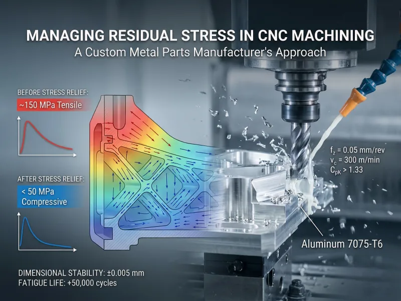
AFI parts recorded exceptional yield rates utilizing these protocols. Dimensional warping decreased by 85%, and dye penetrant inspection revealed zero surface cracks. Spindle load telemetry demonstrated stable cutting forces. Engineers utilized X-ray diffraction to map the machining-induced residual stress pattern, acting as a unique stress fingerprint. The XRD data quantified the exact stress impact of roughing versus finishing passes. Analyzing failed baseline components confirmed that lacking parameter controls generates tensile stress exceeding 100 MPa. High tensile stress lowers the yield point and facilitates structural failure under load. Enforcing strict feed (fz) and speed (vc) limits increased component durability limits.
The data verifies that the locking process variables generate exact dimensional repeatability. This case study validates that managing Residual Stress in CNC Machining produces superior aerospace components. AFI parts standardizes these protocols across all precision manufacturing contracts.
Conclusion
Managing residual stress in CNC machining requires calculating exact parameters. Engineers must specify stable alloys. Programmers must engineer balanced tool paths, and technicians must execute precise thermal processing. Every machining phase alters the stress variables of the subsequent operation. Implementing strict quality control via XRD and telemetry eliminates tolerance deviations. Custom manufacturers achieve CpK > 1.33 stability by deploying targeted stress-relief methodologies and tracking real-time sensor data.
| Process | Purpose | When to Use |
|---|---|---|
| Annealing | Decreases hardness and lowers required cutting force. Homogenizes the grain structure. | Utilize to maximize material removal rates and prepare billets for roughing. |
| Stress Relieving | Neutralizes internal forces following heavy CNC machining, welding, or casting operations. | Decreases hardness and lowers the required cutting force. Homogenizes the grain structure. |
| Recommended Steps for Enhancing Residual Stress Management | Benefits |
|---|---|
| Execute stress-relief annealing prior to final finishing passes (ap < 0.2 mm). | Eliminates Z-axis deflection and stabilizes tool kinematics. |
| Utilize thermal processing to neutralize lattice stress forces. | Maintains 0.005 mm tolerances and locks component profiles. |
| Calculate annealing temperatures based on specific alloy chemistry and tolerance limits. | Decreases insert wear rates and ensures deterministic manufacturing. |
Standardizing these parameters enables AFI parts to deliver components exceeding ISO 9001 quality specifications. Continuously analyzing XRD data and upgrading controller telemetry guarantees residual stress management remains at the forefront of manufacturing technology.
FAQ
Residual stress constitutes internal mechanical forces remaining within a metal lattice following CNC machining material removal. These localized tensile and compressive forces exist without external loads. Exceeding material yield strength limits via these forces causes geometric distortion, surface cracking, and tolerance deviation.
Quality teams deploy X-ray diffraction (XRD) equipment or execute ASTM E837 hole-drilling procedures. These instruments quantify the exact megapascal (MPa) stress load within the lattice. Physical indicators include post-machining geometric warping, structural cracking, or deviations exceeding 0.05 mm.
Multi-axis geometries featuring 1.0 mm thin walls, blind cavities, and 90-degree internal corners trap heat and mechanical forces. Symmetrical block geometries distribute thermal loads evenly. Engineers modify CAD files to maintain uniform wall thickness and insert radii, lowering internal stress limits.
Alloys possessing uniform grain structures and thermal expansion coefficients below 12㎛ / m/m℃ exhibit superior stability. Aluminum 6061-T6 and 316L stainless steels provide reliable baselines. Engineers extract yield strength and thermal conductivity data from material datasheets before programming CNC tool paths.
Executing specific thermal cycles eliminates up to 90% of internal stress limits, but a nominal stress value remains. Integrating annealing prior to the final 0.2 mm finishing pass locks component dimensions. Components exceeding furnace dimensions require vibration stress relief (VSR) or mechanical shot peening.
Yes. High-pressure coolant systems (70 Bar) maintain cutting zone temperatures and evacuate metal chips rapidly. Extracting kinetic heat prevents the material lattice from exceeding thermal expansion limits, halting the generation of stress forces.
Annealing requires elevating alloy temperatures and utilizing a controlled 20°C/hr furnace cooling ramp to decrease hardness and eliminate stress. Normalizing requires heating the alloy above its critical temperature limit and executing ambient air cooling to refine grain boundaries and elevate ultimate tensile strength.
Technicians execute X-ray diffraction or hole-drilling measurements following high-MRR roughing operations and prior to CMM final inspection. Tracking telemetry and metrology data guarantees the component meets aerospace dimensional tolerances and eliminates field failure.
