In the realm of high-precision manufacturing, the difference between a functional component and a scrap part often comes down to microns. As design tolerances for aerospace, automotive, and medical components tighten, traditional linear measurement techniques are no longer sufficient. Coordinate Measuring Machines (CMMs) have evolved from passive inspection tools into active drivers of Volumetric Error Compensation (VEC).
At AFI Industrial Co., Ltd, we understand that machining is not a static process. It is a dynamic interaction of kinematics, thermodynamics, and material science. This article explores the engineering physics behind non-linear errors—specifically investigating geometric, thermal, and dynamic deviations—and details how we utilize closed-loop CMM integration to achieve sub-micron accuracy.
Table of Contents
Impact of Advanced Metrology in Machining Industries
The deployment of advanced metrology is not merely about quality control; it is about process capability optimization. By integrating CMM data directly into the manufacturing execution system (MES), manufacturers can transition from “detection” to “prevention.”
Quality
In the context of AFI Parts‘ production standards, “Quality” refers to statistical process control (SPC). By utilizing CMMs, we move beyond simple Pass/Fail criteria to analyze Cp and Cpk indices. High-precision metrology ensures that the bell curve of production variance remains centered within the tolerance limits defined by ASME Y14.5 GD&T standards.
Exact Measurement
“Exactness” in modern machining implies traceability to international standards (ISO/NIST). Advanced metrology allows for the verification of complex freeform surfaces where linear calipers fail. It ensures compliance with rigorous regulatory frameworks in industries like medical device manufacturing.
Efficiency
Digital metrology reduces the “feedback loop” latency. Instead of waiting for post-process inspection, on-machine verification (OMV) and near-line CMMs provide immediate data, allowing for rapid root-cause analysis of dimensional drift. This significantly reduces machine downtime associated with manual troubleshooting.
Competitiveness
In the custom metal parts market, the ability to guarantee tolerances of ±0.005 mm on complex geometries is a distinct competitive advantage. It allows AFI Parts to bid on high-value contracts that standard machine shops cannot fulfill.
CMMs and Metrology in Machining
CMMs for Non-Linear Error Compensation
Coordinate Measuring Machines are the bedrock of non-linear error compensation. Unlike linear errors (which are proportional to axis travel), non-linear errors arise from complex interactions such as axis straightness deviations, roll-pitch-yaw angular errors, and squareness deviations between axes.
A CMM captures the actual spatial coordinates (x’, y’, z’) of a machined feature and compares them against the nominal CAD coordinates (x, y, z). The deviation vector is calculated as:
Where represents the combined effect of geometric and thermally induced errors. By mapping these errors, we can generate a volumetric compensation map that modifies the CNC controller’s algorithms.
Impact on Machining Precision
Precision is the repeatability of the manufacturing process. CMMs provide the granular data necessary to dissect the “Machine Tool DNA.”
- Dimensional Accuracy: Verifying feature-of-size (e.g., holes, slots).
- Form Accuracy: analyzing circularity, cylindricity, and flatness.
- Positional Accuracy: Verifying True Position under Maximum Material Condition (MMC) modifiers.
When a CMM detects a trend—for example, a gradual drift in the Z-axis due to spindle heating—operators or automated systems can apply a dynamic offset to the tool length compensation, effectively neutralizing the error before it results in a non-conforming part.
Integration with Machining Workflows
At AFI Parts, metrology is not an isolated island. We employ a Closed-Loop Manufacturing System.
- Machining: The CNC machine cuts the part based on the initial G-code.
- Scanning: The CMM scans the part, generating a dense point cloud.
- Analysis: Software (like PC-DMIS or PolyWorks) compares the point cloud to the CAD model.
- Feedback: The deviation data is processed to calculate new coordinate offsets.
- Correction: The G-code or tool offset table is automatically updated for the next cycle.
This integration reduces reliance on operator skill and shifts the burden of accuracy to deterministic algorithms.
Understanding Non-Linear Errors
To fix an error, one must first mathematically define it.
What Are Non-Linear Errors?
In a standard 3-axis machine tool, there are 21 sources of geometric error (also known as parametric errors):
- Linear Positioning Errors (3): Δx(x), Δy(y), Δz(z)
- Straightness Errors (6): Δy(x), Δz(x), Δx(y), Δz(y), Δx(z), Δy(z)
- Angular Errors (Pitch, Yaw, Roll) (9): ϵx(x), ϵy(x), …
- Squareness Errors (3): Sxy, Syz, Szx
Non-linear errors are “non-linear” because they do not scale linearly with position. For example, a guideway might be straight for the first 100mm, then curve by 5 microns, then curve back. Standard pitch error compensation (which assumes linear scaling) cannot fix this. These errors are functions of position, temperature, and kinematic linkage.
Why They Matter in Machining
If ignored, non-linear errors stack up (propagate) through the kinematic chain of the machine.
- Volumetric Accuracy: A machine might be accurate at the origin but deviate significantly at the extremes of the work envelope.
- Complex Geometries: In 5-axis machining, small angular errors in the rotary axes amplify into large positional errors at the tool tip (Abbe Error).
For critical components like hydraulic manifolds or aerospace brackets, a non-linear error of 0.02mm can lead to catastrophic assembly failure or fluid leakage.
Real-World Error Examples
Real-world scenarios at AFI Parts highlight the complexity of these errors:
Abbe Error: This occurs when the measurement axis does not coincide with the axis of the measured part. The error (ϵ) is defined as:
Where L is the offset length (Abbe offset) and θ is the angular error. Even a tiny angular tilt of 5 arc-seconds over a 500mm distance results in a significant positional error.
Hysteresis: The difference in positioning when approaching a point from the positive direction versus the negative direction, often caused by friction or backlash in ball screws.
Comparative Analysis of Measurement Uncertainty:
| Error Source | Manual Tools (Calipers/Micrometers) | CMM (Coordinate Measuring Machine) | Impact on Precision |
| Operator Influence | High (force variation, parallax) | Negligible (automated force modules) | Manual tools introduce variable bias. |
| Cosine Error | Frequent (misalignment) | Minimal (mathematically compensated) | CMMs adjust for the Coefficient of Thermal Expansion (CTE). |
| Temperature | Uncompensated (usually) | Compensated (thermal probes) | CMMs adjust for Coefficient of Thermal Expansion (CTE). |
| Uncertainty ($U$) | ≈ ±0.030 mm | ≈ ±0.002 mm + L/300 | CMMs offer 10x capability. |
CMM Technology in Integrated Metrology

Integrated metrology implies that the measurement system allows for data interoperability with the manufacturing system. This requires robust protocols like I++ DME or QIF (Quality Information Framework) to ensure data integrity from design to inspection.
Types of CMMs and Capabilities
Selection of the correct CMM architecture is critical for the specific application:
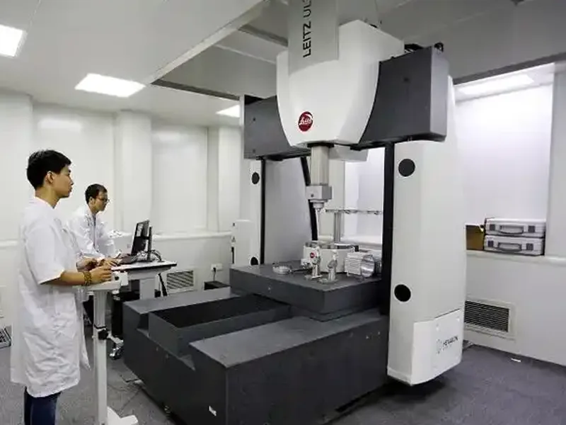
- Bridge CMMs (e.g., Hexagon Global): The industry standard for high accuracy. The moving bridge structure is rigid, minimizing dynamic errors. Best for final inspection of tight-tolerance parts.
- Cantilever CMMs: Open access on three sides makes them ideal for inspecting long parts or integrating into automated loading systems. However, they are structurally less rigid than bridges.
- Horizontal Arm CMMs: Used extensively in the automotive industry for large sheet metal (“Body-in-White”) inspection. They trade some volumetric accuracy for a massive working volume.
- Shop-Floor CMMs (e.g., TIGO SF): Designed with active thermal compensation and pneumatic vibration isolation to operate directly next to CNC machines. They are hardened against dust and oil mist.
Measurement Principles and Data
Modern CMMs utilize discrete point sampling and continuous scanning.
- Discrete Probing: Good for prismatic features (planes, holes).
- Scanning (Analog Probing): Essential for non-linear error detection on freeform surfaces. It collects thousands of points per second to reconstruct the true surface topography.
Scientific Contributions to Error Compensation: Research by Fan et al. and Yang et al. has been instrumental in developing 2D/3D kinematic error models. Their work on multi-probe systems allows for the separation of specific error components (like yaw and straightness), reducing uncertainty to the nanometer level (50nm).
Software and Analysis Tools
The hardware captures the data, but the software creates the value.
- CAD-Based Comparison: Software imports the native STEP or IGES file. It overlays the scanned point cloud onto the CAD model to create a “Color Map” or “Heat Map.” This visualizes non-linear errors instantly—red areas are high (material on), blue areas are low (material off).
- Virtual Alignment: Software performs Iterative Closest Point (ICP) or 3-2-1 alignment algorithms to best-fit the physical part to the digital twin.
Sources of Non-Linear Errors
To compensate effectively, we must isolate the root causes.
Machine Tool Geometric Errors
These are inherent to the machine’s construction.
- Guideway Straightness: No rail is perfectly straight.
- Orthogonality: The X, Y, and Z axes are never perfectly 90° to each other.
We model these using Homogeneous Transformation Matrices (HTM). The position of the tool tip relative to the workpiece is the product of the transformation matrices of each axis. An error in one matrix propagates through the chain.
RTt = RTx • xTy • yTz • zTt
Geometric error measurement allows us to populate the error terms within these matrices.
Thermal and Kinematic Influences
Thermodynamics is the enemy of precision.
Internal Sources: Spindle bearings, axis motors, and gearboxes generate heat.
Expansion: A steel leadscrew will expand approximately 11.7㎛ per meter per degree Celsius ℃
ΔL = L • α • ΔT
If a ball screw heats up by 10℃, a 1-meter travel introduces an error of ≈117㎛, which is massive in precision machining.
Kinematic Errors: As the machine moves, the weight of the carriage can deform the guideways (gravity sag). This is a non-linear error that changes based on the position of the axes.
Material and Process Deviations
Tool Wear: As a cutter wears, its diameter decreases (radial wear), and its length decreases (axial wear). This creates a progressive, non-linear error trend.
Deflection: Cutting forces cause the tool to bend (cantilever beam deflection). Δ = . Harder materials (like Inconel or Titanium) induce higher forces, causing more deflection and non-linear surface errors.
CMM-Based Error Compensation Methods
At AFI Parts, we employ a multi-tiered approach to compensation.

Calibration and Reference Standards
Before measuring parts, we must measure the machine. We utilize Laser Interferometry and Ball Bar Testing to characterize the CMM and CNC machines.
- Volumetric Error Mapping: A laser tracker or interferometer measures the machine’s positioning at hundreds of points within the work volume.
- Artifact Verification: We measure calibrated artifacts (step gauges, ring gauges) traceable to NIST/PTB standards to verify the compensation map.
Error Mapping and Analysis
We create a Voxel Map of the machine’s workspace.
- Divide the workspace into a 3D grid (e.g., 50mm x 50mm x 50mm cubes).
- Measure the error vector at each node.
- Interpolate errors between nodes using Chebyshev polynomials or B-splines. This allows the controller to know the exact error at any point in the space, not just the measured points.
Software Compensation Strategies
There are two primary strategies we employ:
- Feedforward Compensation (Pre-Process): We modify the G-code before machining. If we know the machine has a +0.01mm error at X=100, we program the cut to go to X=99.99. This assumes the errors are repeatable (systematic).
- Feedback Compensation (Real-Time/Inter-Process): We probe the part while it is still clamped in the machine (On-Machine Verification). The deviation is sent to the CNC controller to update the Work Coordinate System (G54-G59) or Tool Offset Table. This compensates for thermal drift and tool wear that occurred during the cut.
Comparison of Strategies:
| Feature | Feedforward (G-code Mod) | Feedback (Offset Update) |
| Target Error | Geometric, Static | Thermal, Tool Wear, Dynamic |
| Response Time | Pre-calculated | Near Real-time |
| Complexity | High (requires error map) | Medium (requires probing macro) |
| Suitability | High-volume production | High-value, low-volume parts |
Environmental Controls
Precision cannot exist in chaos. The “Standard Reference Temperature” for dimensional metrology is 20℃ (68℉). Deviations from this baseline require complex compensation.
Key Environmental Factors Affecting CMM Performance:
- Thermal Gradients: It is not enough to be at 20℃. The temperature must be uniform. A gradient (e.g., cold air blowing on one side of a CMM granite table) causes bending (bimetallic strip effect).
- Humidity: High humidity causes corrosion on steel guideways. Low humidity (<30%) causes static electricity discharge, which can damage sensitive CMM probe electronics.
- Vibration: Seismic vibrations from nearby stamping presses or forklifts introduce noise into the CMM readings. We use passive air mounts and active piezo-electric damping to isolate our CMMs.
Best Practices for Environmental Control
AFI Parts maintains a Class 10,000 cleanroom environment for final inspection:
- Temperature Stabilization: ±0.5℃ per hour.
- Air Flow: Laminar flow to prevent turbulence and thermal pockets.
- Soak Time: Parts are allowed to “soak” in the lab for 24 hours prior to measurement to reach thermal equilibrium.
Diagnostics, Troubleshooting, and Maintenance

Routine CMM Maintenance
A CMM is a precision instrument that requires rigorous care.
- Air Bearings: The CMM floats on a cushion of compressed air (approx. 5 microns thick). The air supply must be ultra-pure (ISO 8573-1 Class 4) to prevent clogging the porous media.
- Stylus Qualification: The ruby or silicon nitride stylus tip must be perfectly spherical. We routinely check for “flat spots” caused by scanning hard materials.
Troubleshooting Measurement Issues
When a measurement fails, we follow a rigorous Root Cause Analysis (RCA) methodology (e.g., Fishbone Diagram):
- Isolate: Is the error in the part, the fixture, or the CMM?
- Verify: Remeasure a known artifact (Master Ring). If the ring measures correctly, the CMM is likely fine.
- Inspect Fixturing: Is the part clamped too tightly? (Elastic deformation). Is there debris on the datums?.
Recommendations for Machining Professionals

Implementing CMM Compensation
For engineers looking to implement this workflow:
- Characterize Your Machine: Do not assume your CNC is perfect. Use a ball bar to check circularity.
- Establish a Golden Part: Machine a part, measure it on a calibrated CMM, and use it to “teach” the on-machine probe.
- Focus on Datums: Non-linear errors often manifest as poor alignment. Ensure your primary, secondary, and tertiary datums are robust.
Training and Skill Development
The hardware is only as good as the operator. We invest heavily in training:
- GD&T (ASME Y14.5): Understanding Maximum Material Boundaries (MMB) and datums.
- Metrology Software: Advanced training in PC-DMIS, PolyWorks, or Calypso.
- Statistical Analysis: Understanding measurement uncertainty budgets U = k • uc).
Continuous Process Improvement
We adopt the Deming Cycle (PDCA):
- Plan: Define the measurement strategy.
- Do: Execute the CMM routine.
- Check: Analyze the error map.
- Act: Update the CNC compensation tables.
Conclusion
At AFI Industrial Co., Ltd, we do not view non-linear errors as unavoidable nuisances, but as variables to be modeled, measured, and mastered. By integrating advanced Coordinate Measuring Machines into a closed-loop manufacturing ecosystem, we neutralize the geometric, thermal, and kinematic errors inherent in metalworking.
This commitment to Advanced Metrology allows us to deliver custom metal parts that meet the most demanding specifications of the global market. Whether it is aerospace titanium or medical-grade stainless steel, our data-driven approach ensures that every micron is accounted for.
FAQ
CMMs check parts while machines are working. They find mistakes early. This helps every part match the design. CMMs make things more accurate and cut down on waste.
CMMs make checking parts more trustworthy. They look at each part and compare it to the plan. This keeps quality high and helps track each part in advanced manufacturing.
Traceability connects each part to its measurement numbers. This helps workers find where mistakes start. It also helps with checks and audits in advanced manufacturing.
Uncertainty means there could be a small mistake in a measurement. If uncertainty is low, workers can trust the results more. This is important for making parts that fit well.
Yes. CMMs can check metals, plastics, and composites. This means they work for many jobs and help lots of industries.
Advanced manufacturing uses CMM data to change how machines work right away. This makes work faster and helps every part meet tough rules.
