In the realm of high-precision custom manufacturing, surface finish is rarely just an aesthetic choice; it is a critical engineering specification that dictates mechanical performance, seal integrity, and component longevity. While standard CNC milling might yield a surface roughness average (Ra) of 1.6 to 3.2 μm, mission-critical applications in aerospace, medical devices, and semiconductor manufacturing frequently demand surfaces smoother than Ra 0.4 μm (approx. 16 μin).
At AFI Parts, we view surface finishing not as a post-processing afterthought, but as an integral phase of the manufacturing lifecycle. Achieving a sub-micron finish requires a holistic control of the machining environment—from toolpath strategy and coolant filtration to the granular mechanics of abrasive media.
This engineering guide details the methodologies we employ to achieve Ra 0.4 μm and finer, supported by our internal process data and adherence to ISO 21920 and ASME B46.1 standards.
Table of Contents
Surface Quality in Metal Manufacturing
When we discuss “quality” in metal manufacturing, we are referring to the geometric irregularities of a surface. To the naked eye, a part may look “shiny,” but under a profilometer, that same surface may resemble a jagged mountain range.

What Ra 0.4 Means for Parts
Ra (Roughness Average) is the arithmetical mean deviation of the assessed profile. Mathematically, it calculates the average distance of peaks and valleys from the mean line within a sampling length.
A Ra 0.4 μm finish represents a critical threshold in manufacturing. It is the transition point where a surface shifts from “mechanically smooth” to “hydraulically/pneumatically tight.”
- Visual Appearance: At Ra 0.4 μm, machining marks become barely visible to the naked eye. The surface begins to exhibit reflective properties, though it is not yet a true mirror (which typically starts at Ra 0.1 μm or N3 grade).
- Tactile Feel: The surface feels completely smooth, with no snagging of a fingernail or probe.
However, relying solely on Ra can be misleading. A surface can have a low Ra but still possess deep, narrow valleys that compromise fatigue strength. This is why AFI Parts emphasizes comprehensive topology analysis.
Field Note: In a recent project for a hydraulic spool valve, a competitor provided a part with Ra 0.35 μm that failed leakage tests. Why? Their process left deep transverse scratches (high Rz). AFI Parts achieved Ra 0.4 μm using a cross-hatch honing pattern, which retained lubrication oil while providing a superior seal, proving that how you achieve the number matters as much as the number itself.
Why Surface Finish Matters
Surface topology directly influences the tribological system—the interaction of surfaces in relative motion.
- Friction and Heat Generation: A rougher surface has higher asperity peaks. When two surfaces slide against each other, these peaks interlock, shear off, and generate heat. Reducing Ra from 1.6 μm to 0.4 μm can reduce the coefficient of friction by upwards of 30% in lubricated conditions, significantly lowering operating temperatures.
- Fatigue Life: Micro-cracks often initiate at the “valleys” of surface roughness. In high-stress cyclic loading (e.g., aerospace turbine blades), a deep tool mark acts as a stress riser. Polishing to Ra 0.4 μm eliminates these initiation sites, extending fatigue life.
- Cleanability: In pharmaceutical and food processing, rough surfaces harbor bacteria. Ra 0.4 μm is generally the maximum allowable roughness for 3A Sanitary Standards.
The table below outlines the direct correlation between surface finish specifications and mechanical performance based on AFI Parts’ internal testing data.
Table 1: Impact of Surface Finish on Mechanical Properties
| Aspect | Metric Impacted | Engineering Justification | Typical Specification |
| Corrosion Resistance | Salt Spray Hours | Smoother surfaces have less surface area exposed to oxidation and fewer crevices for pitting initiation. | Ra < 0.4 μm |
| Wear Resistance | Bearing Area Ratio (tp) | Higher contact area distributes the load more evenly, preventing adhesive wear and galling. | Ra 0.2 – 0.4 μm |
| Dimensional Accuracy | Tolerance Stack-up | Surface roughness is effectively “noise” in measurement. A rough surface makes precise tolerancing (e.g., ±5 μm) impossible to verify reliably. | Ra ≤ 10% of Tolerance |
| Fatigue Strength | Cycle Life | Reduction of notch sensitivity. Polished surfaces withstand higher tensile loads. | Ra < 0.2 μm |
Applications Requiring Ultra-Smooth Surfaces
While general automation components function well at Ra 1.6 μm, specific industries demand the ultra-smooth surfaces we specialize in at AFI Parts.
- Semiconductor Manufacturing: Gas delivery systems require electropolished stainless steel (Ra < 0.15 μm) to prevent outgassing and particle generation. Even a microscopic burr can cause a short circuit in wafer processing.
- Medical Implants: Titanium bone screws and hip joints require specific finishes. Interestingly, some areas need roughness for osseointegration, while articulating surfaces must be mirror-polished (Ra < 0.05 μm) to prevent polyethylene wear debris.
- Aerospace Hydraulics: Actuators operating at 5000+ psi rely on elastomer seals. A finish that is too rough shreds the seal; a finish that is too smooth (Ra < 0.1 μm) causes “stick-slip” phenomena because the seal cannot ride on a hydro-dynamic film of oil. Ideally, we target Ra 0.2–0.4 μm for these dynamic applications.
- Plastic Injection Molding: Mold cavities often require SPI A-2 or A-1 finishes (Ra 0.05–0.025 μm) to ensure the plastic part releases easily and has a glossy cosmetic appearance.
Advanced Techniques for Mirror Finishes in Machined Parts
Achieving a mirror finish is a subtractive process that becomes increasingly delicate as you approach the target roughness. It is not simply about “polishing harder”; it is about sequentially reducing the peak-to-valley height without altering the dimensional geometry of the part.
At AFI Parts, we employ a tiered approach to finishing, selected based on the material substrate and the part geometry.
High-Speed Machining and 5-Axis CNC
The journey to a mirror finish begins with the primary machining operation. You cannot efficiently polish a part that has deep chatter marks or scallops.
High-Speed Machining (HSM) minimizes chip load and heat generation. By utilizing spindle speeds exceeding 20,000 RPM and high feed rates with low depths of cut (trochoidal milling), we reduce the cutting force.
- Vibration Control: We use balanced tool holders (Haimer shrink-fit) and solid carbide end mills with variable helix angles to dampen harmonic vibrations.
- Scallop Height Control: On curved surfaces, the “step-over” distance determines roughness. Using a 5-axis machine allows us to keep the tool normal to the surface, utilizing the bottom radius of the end mill rather than the side. This reduces the theoretical scallop height to negligible levels.
AFI Process Insight: For 6061 Aluminum optical housings, we utilize a mono-crystalline diamond tool on our 5-axis Makino. This allows us to achieve Ra 0.1 μm directly off the machine, eliminating secondary polishing that could distort the lens flatness.
Table 2: ROI and Capability Analysis of CNC Architectures
| Machine Architecture | Investment Range (USD) | Geometric Capability | Surface Finish Limit (As-Machined) | Operator Expertise Required |
| 3-Axis Vertical | 60k – 150k | Prismatic parts | Ra 1.6 – 0.8 μm | Entry/Intermediate |
| 3+2 Axis Indexing | 120k – 250k | Multi-sided parts | Ra 0.8 – 0.6 μm | Intermediate |
| Simultaneous 5-Axis | 350k – 750k+ | Complex contours, Impellers | Ra 0.4 – 0.1 μm | Advanced (Mastercam/Hypermill) |
Precision Grinding and Reaming

When geometric tolerances are as tight as surface finish requirements (e.g., a shaft diameter ±0.002 mm), grinding is the preferred method.
- Cylindrical Grinding: Using CBN (Cubic Boron Nitride) wheels, we can consistently hold Ra 0.2 μm on hardened steel shafts (HRC 58-62). The key is the “spark-out” pass, where the wheel traverses the part with zero in-feed, removing only the elastic deformation of the material.
- Jig Grinding: For internal holes that require perfect roundness and finish, jig grinding achieves Ra 0.1 μm.
- Reaming: While generally considered a rougher operation, utilizing floating reamers with diamond-tipped edges can achieve Ra 0.4 μm in aluminum and brass, provided the coolant pressure is sufficient to evacuate chips immediately.
Process Parameter Example:
- Operation: Surface Grinding D2 Tool Steel
- Wheel: 46 Grit Aluminum Oxide (Roughing) -> 120 Grit (Finishing) -> 400 Grit (Super-finish)
- Result: Ra 0.05 μm achieved with flood coolant filtration to 5 microns.
Metal Media Tumbling and Micro-Polishing
Mass finishing is essential for consistency across large batches. It removes directional tool marks and produces an isotropic (non-directional) finish.
- Centrifugal Barrel Finishing: This high-energy process subjects parts to up to 25G forces. It is significantly faster than vibratory tumbling.
- Media Selection:
- Ceramic Media: Aggressive, good for deburring steel.
- Plastic/Synthetic: Softer, creates lower Ra, prevents impingement on soft metals like aluminum.
- Walnut Shell/Corn Cob: Used with polishing pastes for the final “luster.”
Data from AFI Internal Trials (SS316L Brackets):
| Process Stage | Cycle Time | Initial Ra (μm) | Final Ra (μm) | Material Removal |
| Vibratory Tumble (Ceramic) | 4 Hours | 3.2 | 0.9 | 15 μm |
| High-Energy Centrifugal (Plastic) | 45 Mins | 0.9 | 0.35 | 5 μm |
| Dry Organic Polish (Walnut) | 2 Hours | 0.35 | 0.15 | < 1 μm |
Note: The “Sz” (Maximum Height) is often drastically reduced in the first stage, smoothing the peaks, while subsequent stages reduce the Ra.
Electropolishing and Isotropic Superfinishing
For the ultimate clean, we turn to chemical and electrical processes.
Electropolishing (EP) is essentially “reverse plating.” The part is submerged in an electrolyte bath (typically phosphoric/sulfuric acid) and subjected to a DC. The current density is highest at the microscopic peaks of the surface profile, causing them to dissolve faster than the valleys.
- Benefits: Removes the amorphous layer (Beilby layer) created by machining stress. It improves corrosion resistance by enriching the chromium oxide layer on stainless steel.
- Limit: EP typically reduces roughness by 50%. If you start with Ra 1.0, you get Ra 0.5. To get Ra 0.1, we must mechanically polish to Ra 0.2 first.
Isotropic Superfinishing (ISF/REM): This is a chemically accelerated vibratory process. It uses a mild acid to form a soft conversion coating on the metal, which is then wiped off by non-abrasive media. It creates a distinct “non-directional” surface texture that retains lubrication oil exceptionally well.
Ultrasonic and Hybrid Methods

Ultrasonic machining is a cutting-edge technique where the tool or the workpiece oscillates at ultrasonic frequencies (15–40 kHz) with small amplitudes (1–10 μm).
- Ultrasonic Polishing: A diamond tip vibrates ultrasonically. This hammering action breaks down surface peaks effectively on hard materials like Tungsten Carbide or hardened molds.
- Hybrid Efficiency: When combined with CNC milling, ultrasonic vibration reduces cutting resistance by up to 40%, allowing for better surface finishes on difficult alloys like Inconel 718.
Material and Surface Considerations for Quality Parts
A frequent oversight in design is specifying a surface finish that the material cannot support. Not all metals can be polished to a mirror.
Substrate Material Impact on Surface Finish
Grain Structure: Inclusions limit achievable smoothness. For example, Stainless Steel 303 contains sulfur to improve machinability (making chips break easily). However, under high magnification polishing, these sulfur pockets tear out, leaving microscopic pits (“comet tails”). Therefore, Stainless Steel 304 or 316L (Vacuum Melted) is mandatory for Ra < 0.2 μm semiconductor parts.
Hardness: Soft materials (pure Copper, soft Aluminum) tend to “smear” rather than cut during polishing. Harder materials (Tool Steel, Titanium) generally accept a crisper, brighter polish.
Matching Techniques to Metal Types
At AFI Parts, we customize the process map based on the alloy:
Table 3: Optimized Finishing Protocols by Alloy
| Alloy Family | Recommended Finishing Strategy | Common Pitfalls | Best Achievable Ra |
| Aluminum (6061/7075) | Diamond Turning or Chemical Bright Dip | Galling/Smearing if the abrasive is too fine or the heat is too high. | 0.05 μm |
| Stainless Steel (304/316) | Electropolishing or Centrifugal Tumbling | Work hardening. requires aggressive initial cut followed by EP. | 0.02 μm |
| Titanium (Gr5) | Vibratory Finishing with Acid Accelerators | High friction coefficient causes overheating and surface “orange peel.” | 0.2 μm |
| Tool Steel (D2/A2) | Precision Surface Grinding + Lapping | Oxidation if coolant is insufficient. | 0.01 μm |
Pre-Finishing and Preparation Steps
You cannot cheat the physics of finishing. Attempting to jump from a rough milled surface (Ra 3.2) directly to a diamond buff (Ra 0.1) will result in a “cloudy” finish. The surface will look shiny but will be full of deep scratches covered by smeared metal.
The Rule of Steps: We typically recommend stepping down abrasive grit sizes by no more than 2x per step.
- Level 1 (Machining): Target Ra 1.6 μm.
- Level 2 (Grinding/Sanding): 320 Grit -> Target Ra 0.8 μm.
- Level 3 (Fine Sanding): 600 Grit -> Target Ra 0.4 μm.
- Level 4 (Pre-Polish): 1200 Grit or Cut Buff -> Target Ra 0.1 μm.
- Level 5 (Final Polish): Diamond Paste or Color Buff -> Target Ra 0.05 μm.
Thorough cleaning between steps is non-negotiable. A single grain of 320 grit carried over to the 1200 grit stage will ruin the entire batch, creating “tracer” scratches that require restarting the process. We utilize multi-stage ultrasonic cleaning tanks with deionized water to ensure zero cross-contamination.
Quality Control and Measurement of Surface Finishes
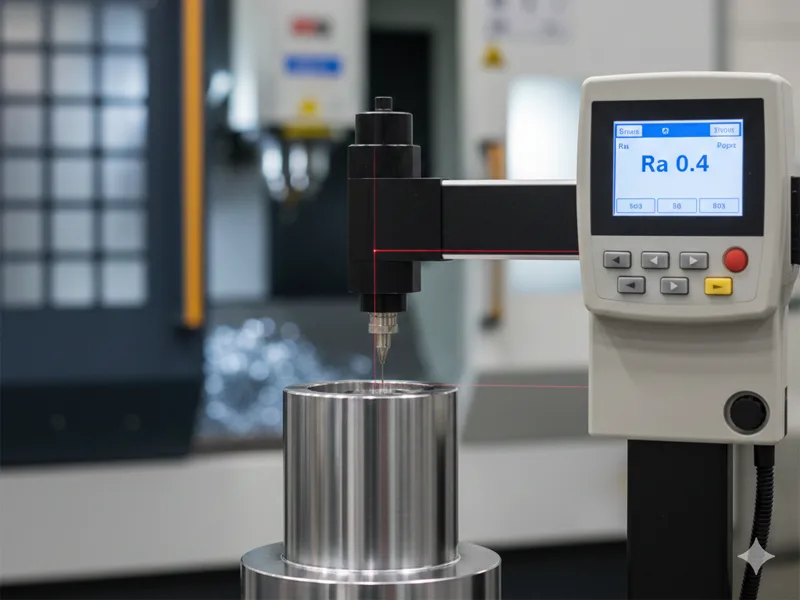
Verifying Ra 0.4 μm requires metrology equipment capable of resolving micro-inches.
Surface Roughness Measurement Tools

Contact Profilometers (Stylus): The industry workhorse. A diamond stylus drags across the surface.
- Pros: Direct measurement, adheres to ISO standards.
- Cons: Can scratch soft materials (copper/gold); only measures a 2D line, potentially missing defects adjacent to the path.
Optical Profilometers (White Light Interferometry):
- Pros: Non-contact, measures a 3D area, can separate roughness from waviness.
- Cons: Expensive, sensitive to reflectivity differences.
Comparators: Visual/Tactile plates. Useful for quick “Go/No-Go” checks on the shop floor but insufficient for certifying Ra 0.4 μm specs.
Key Parameters Beyond Ra
Engineering drawings often default to Ra, but at AFI Parts, we analyze the Abbott-Firestone Curve and other parameters to predict part behavior:
- Rz (Mean Roughness Depth): The average of the highest peaks and lowest valleys. A surface can have a good Ra (0.4) but a bad Rz (4.0) if there are occasional deep scratches. High Rz leads to seal failure.
- Rpk (Reduced Peak Height): Represents the peaks that will be worn away during the “break-in” period of a bearing.
- Rvk (Reduced Valley Depth): Represents the valleys that retain lubricant. For an engine cylinder liner, we actually want a specific Rvk to hold oil, even if the Ra is low.
Preventing Defects in Metal Manufacturing
High-quality finishing exposes underlying manufacturing defects. A mirror polish acts as a magnifying glass for metallurgical flaws.
Common Defects Exposed by Polishing
- Porosity: In casting or poor welds, polishing opens up sub-surface gas pockets. What looked like solid metal suddenly has pinholes.
- Prevention: Use Vacuum Degassing during casting or specify forged/Billet material for critical polished parts.
- Orange Peel: A wavy, dimpled surface texture caused by overheating the material during buffing or using a polishing wheel that is too soft/slow.
- Prevention: Increase oscillation speed, reduce pressure, and ensure the material grain size is fine.
- Comet Tails: Caused by inclusions (impurities) in the metal, dragging across the surface during polishing.
- Prevention: Switch to ESR (Electro-Slag Remelted) grade steels for mold cavities.
Table 4: Troubleshooting Surface Finish Defects
| Defect Manifestation | Root Cause | Corrective Action |
| Cloudiness / Haze | Skipping abrasive steps; Sub-surface damage. | Return to previous grit size; Clean thoroughly between steps. |
| Pitting | Corrosion; Over-electropolishing; Material inclusions. | Check electrolyte specific gravity; Switch to Vacuum Arc Remelted (VAR) material. |
| Chatter Marks | Machine vibration; Tool deflection. | Increase system rigidity; Use variable helix end mills; Check spindle runout. |
| Scratch Patterns | Dirty media; Contaminated buffing wheels. | Implement clean room protocols for the final finishing area. |
Conclusion: The AFI Parts Commitment
Achieving a surface finish of Ra 0.4 μm is not magic; it is the result of rigorous process control, material science expertise, and advanced equipment. Whether using 5-axis CNC machining, precision grinding, or electropolishing, the goal remains the same: to produce parts that perform flawlessly in their intended environment.
At AFI Parts, we verify every critical surface with calibrated profilometers and provide detailed inspection reports. As manufacturing moves toward miniaturization and higher performance standards, our investment in advanced finishing technologies ensures your components meet the specifications of tomorrow.
FAQ
Generally, moving from a standard milled finish (Ra 1.6) to a fine finish (Ra 0.4) can increase part cost by 20-50%, depending on geometry. This is due to slower machine run times (finishing passes) or the addition of a secondary operation like grinding. However, this cost is often offset by the elimination of manual benchwork or improved system reliability.
Raw DMLS parts typically have a roughness of Ra 10-15 μm. Achieving Ra 0.4 is possible but requires significant post-processing, usually involving CNC machining of critical features followed by media tumbling or electropolishing. We recommend designing extra “stock” material on surfaces that need this finish.
Passivation utilizes acid to remove free iron from the surface to prevent rust; it does not significantly change surface roughness. Electropolishing removes material to smooth the surface (improving Ra) and passivates it simultaneously. Electropolishing is the superior choice for high-purity applications.
To avoid ambiguity, specify the standard (e.g., ASME B46.1), the parameter (Ra, Rz), the value (0.4 μm), and the manufacturing method if necessary (e.g., “Ground to Ra 0.4 MAX”). Also, indicate “Lay” symbols if the direction of the finish matters for sealing.
