In the highly competitive field of precision CNC machining and custom metal fabrication, omitting grain direction verification during raw material routing is a critical engineering oversight. Imagine a custom metal products manufacturer that does not check grain direction in raw material routing. This mistake can cause expensive problems and less accuracy, as grain orientation inherently dictates the mechanical anisotropy of the workpiece, changing how well things are made and how long they last. Manufacturers make routing better by systematically checking grain direction for every custom part prior to entering the CNC or stamping queue.
This rigorous adherence helps them get better accuracy and significantly stronger results. For instance, empirical data demonstrates that turning stainless steel blanks 90 degrees relative to the rolling direction lowers cracking and deep-draw defects by 15%. Furthermore, strategically orienting the grain at 45 degrees to the primary axis of strain cuts cracking by 20% in hard, complex custom shapes. Custom metal products manufacturer teams use strict accuracy and smart engineering to give good custom solutions that meet stringent aerospace and automotive standards.
Key Takeaways
- Grain direction changes how strong and tough metal parts are; engineers must always look at it before starting to make anything to avoid catastrophic failure.
- Turning stainless steel blanks by 90 degrees can cut down forming defects by 15%.
- This easy, quantifiable step makes the quality better and reduces scrap rates.
- Bending metal across the grain (perpendicular to the rolling direction) is safer for the part, as it lowers the risk of intergranular cracks, especially in strong, high-yield steels.
- Utilizing advanced CAD and CAM software to plan toolpaths and show grain direction helps stop costly mistakes when using multi-axis CNC machines.
- Workers need regular training about grain direction to understand its impact on material yield.
- This holistic approach helps them make better parts and have fewer routing errors.
- Quality checks like ultrasonic (UT) and magnetic particle inspections (MPI) check grain alignment and help find micro-fissure problems early.
- Enterprise Material Tracking Systems (ERP/MRP) keep grain direction clear during production, which helps keep quality high and work fast.
- Always try to improve how you make things, which leads to better geometric accuracy and fewer mistakes over time.
Table of Contents
Grain Direction Basics
What Is Grain Direction?
Grain direction shows how the inside of metal lines up when it is made. When metal is shaped, the grains make patterns that match the way it was formed. Grain direction shows how the inside crystalline structure of metal lines up when it is made at the mill. When metal is plastically deformed—shaped, rolled, or drawn—the individual metallic grains elongate, creating patterns that match the way it was worked. This crystallographic texture means that grain direction changes how metal acts when pushed or pulled (anisotropy).
For example, the ultimate tensile strength (σUTS) and yield strength (σy) will vary depending on the testing angle relative to the rolling direction. Engineers need to deeply think about grain direction to keep metal strong and long-lasting under cyclic fatigue. In custom metal fabrication, grain direction helps decide exactly how to cut, bend, or shape the metal workpiece. It is very important to make metal parts safe and ensure they work well in their final assembly.
Tip: Always look at grain direction before you start making metal parts. This vital quality control step stops weak spots and makes custom metal parts significantly better.
How Grain Forms in Metal Fabrication
The specific way metal is made at the foundry changes the grain direction, whether by rolling, pressing (forging), or extrusion. Cold or hot rolling stretches the inside lattice of the metal and makes long, fibrous grains; these grains go the same way as the rolling equipment. Consequently, this makes the metal act differently depending on which way you push, pull, or shear it.
For example, bending metal with (parallel to) the grain causes localized stress concentrations that can make it crack along the grain boundaries. Conversely, bending across the grain spreads out the tensile force and makes the metal much stronger at the bend radius. Metal engineering design teams use this fundamental metallurgical principle to plan how to make each part and pick the best grain direction.
Metal Fabrication Process and Grain Direction Outcome:
- Rolling: Grains align longitudinally with the roll direction, creating a strong anisotropic flow.
- Pressing (Forging): Grains follow the pressure of the die, creating uninterrupted flow lines that contour the part geometry.
- Extrusion: Grains stretch intensely along the flow axis, maximizing tensile strength in the extruded direction.
Designers need to know exactly how each way of making metal changes grain direction. This engineering foresight helps them make parts that are strong enough to withstand operational loads.
Identifying Grain in Custom Metal Parts

Finding grain direction in custom metal fabrication is absolutely important for maintaining good quality and surface roughness standards. Manufacturers look at the raw metal, use chemical etching (e.g., using Nital for steel or Keller’s reagent for aluminum), or magnify it under a metallurgical microscope to see exact grain patterns. Often, to the trained eye, you can see faint lines or streaks on the metal’s surface indicating the rolling direction.
At AFI Parts, engineers meticulously mark the grain direction on the raw stock before they start making the part. This mandatory protocol makes sure every CNC cut, press brake bend, or TIG weld goes the right way. Metal engineering design teams need to find the grain direction to stop machining mistakes and make final products last longer in the field.
- Visual inspection: Shows macro grain lines on the raw stock.
- Etching makes grain patterns easy to see.
- Magnification: Lets metallurgists accurately see the grain structure and measure grain size (e.g., per ASTM E112).
Knowing the grain direction optimizes the entire metal fabrication process and keeps the metal structurally strong. It also dramatically lowers the chance of programming mistakes and makes custom metal parts work better under dynamic loads.
Grain Direction & Strength
Structural Integrity in Metal Fabrication
Grain direction is very important for dictating how strong custom metal parts are under applied mechanical stress. When elongated grains go the same way as the primary operational force, the load is distributed along unbroken boundaries, meaning the part gets stronger and works better. Engineering teams strictly check grain orientation before they start making the part to align these load paths. This preemptive analysis helps stop internal weak spots and keeps the final part safe from catastrophic failure.
The table below shows how grain direction changes different things about strength in metal parts:
| Aspect | Effect on Structural Integrity |
|---|---|
| Strength | Proper grain alignment enhances strength and toughness. |
| Fatigue Resistance | Aligned grains minimize points of crack initiation, reducing fatigue failure. |
| Durability | Enhanced grain flow leads to longer lifespan under cyclic loads. |
| Impact Absorption | Grains oriented in the same direction improve impact resistance. |
| Abrasion Resistance | Parallel grains distribute stress evenly, increasing resistance to wear. |
Custom machining shops use this critical engineering information to plan their manufacturing work. By thinking mathematically about grain direction, they make metal parts last longer and work better in their intended environments.
Impact on Bending and Forming

Bending and shaping metal via press brakes or stamping dies heavily depends on grain orientation. Sheet metal (like 304L SS or 6061-T6 Al) gets a very clear, defining grain direction when it is rolled at the mill. If a CNC programmer or brake operator does not pay attention to this, the metal can break or spring back in ways you do not expect.
To calculate the Bend Allowance (BA) accurately, engineers must account for the material’s anisotropic K-factor, utilizing the formula:
where A is the bend angle, R is the inside radius, K is the K-factor, and T is the material thickness. This calculation shifts depending on orientation. Engineering teams inherently know that bending metal strictly across the grain lowers the chance of outer-fiber cracks. Bending with the grain makes transverse cracks far more likely, especially in strong, high-carbon steels.
- Sheet metal has a permanent grain direction inherited from cold rolling.
- Not checking grain orientation can cause expensive surprise breaks during forming.
- Bending at a precise 90-degree angle to the grain is mathematically safer.
- Bending with the grain can cause immediate breaks, especially in strong steel alloys.
- Planning CAM simulations carefully helps teams avoid big production mistakes.
Engineering Design Rule: Calculating Bending Tonnage Variations
Grain orientation directly impacts the required bending force. When pressing sheet metal across the grain (perpendicular), the ultimate tensile strength in the localized bend zone is marginally higher, requiring more tonnage but yielding a significantly safer bend radius. The bending force F can be quantified using:
$$F = \frac{K \cdot L \cdot S_{ut} \cdot t^2}{W}$$
Where L is the bend length, Sut is the ultimate tensile strength, t is the material thickness, W is the die opening, and K is the die constant. At AFI Parts, we account for a 5% to 8% variation in Sut depending on whether the bend is parallel or perpendicular to the rolling direction, and we adjust our press brake crowning systems accordingly to prevent edge cracking in high-yield steels.
Manufacturing teams use these physics-based rules to ensure every part is strong and safe.
Residual Stress and Cracking
If the grain is not lined up right during the initial CAD routing, big structural problems can happen later. For instance, in forging operations, if the billet is not set the right way within the die, the metal’s plastic flow gets severely messed up. This misalignment makes weak spots and spreads mechanical stress highly unevenly; because of this, massive residual stress builds up inside the core of the part.
To quantify the risk, the stress intensity factor at a micro-crack tip can be evaluated as:
$$K_I = Y \sigma \sqrt{\pi a}$$
Stress Intensity Factor (KI) Verification Tools
A Fracture Mechanics Quick Calculator Designed Specifically for Mechanical Design Engineers. This tool uses a formula KI = Y σ √(πa)
where σ is the applied stress, and a is the crack length. Misaligned grains increase local σ, meaning over time, this stress can make cracks form rapidly, and the part will not last as long. Engineering teams rigorously monitor grain orientation at every step to prevent these fracture-mechanics problems. Good, controlled work keeps dangerous cracks away and helps custom metal parts stay reliable and strong.
Custom Metal Products Manufacturer's Production Challenges
Material Sourcing & Variability

Manufacturing supply chains and procurement teams have many inherent problems when getting raw materials from metal fabrication. Suppliers sometimes send sheet or bar stock materials with completely different, unmarked grain directions, and this change makes it hard to keep CNC metal production the same every time. Quality engineers need to inspect and check each inbound batch to make sure the grain direction is right for the custom parts being machined.
If the grain direction is not perfectly the same in every batch, configuring CNC offsets and making parts can abruptly slow down. Teams use careful inbound QA checks to keep production fast and smooth. They watch materials systematically from when they arrive on the dock until the last assembly step. This strict oversight stops weak spots in metal parts and helps things run much better.
Note: When grain direction stays consistent and the same, production cycle times are faster and there are mathematically fewer geometric mistakes in metal fabrication.
Manufacturing companies trust good, ISO-certified suppliers to help stop unexpected changes in grain direction. They use advanced quality control systems (like APQP and PPAP frameworks) to precisely check materials during every step. These robust actions help keep CNC processes running well and make sure final metal parts are structurally strong.
Multi-Part Assembly Issues
Making complex assemblies with many interacting metal parts needs exceptionally good CAD planning. Every single welded or bolted part must have the right grain direction aligned to keep the overarching structural integrity of the final unit. If the grain direction is wildly different in each mating part, serious thermal expansion or load-bearing problems can happen when putting them together. Teams must carefully line up grain direction for all constituent pieces to stop weak, failure-prone joints and stress cracks.
The table below shows how grain direction changes bending dynamics in custom metal fabrication assemblies:
| Grain Direction | Impact on Bending Properties |
|---|---|
| Parallel | Bend radius changes more unpredictably, and severe intergranular cracks can happen. |
| Perpendicular | Plastic deformation (bending) is significantly more even and mathematically steady. |
| Diagonal | Bending springback and cracking risk is precisely between parallel and perpendicular values. |
Manufacturing engineering teams actively use this empirical chart to make production sequencing better. They selectively pick materials with the same grain direction for each sub-assembly. This strategy lowers the chance of welding mistakes and helps metal production go much faster. Engineers use 3D modeling to plan how to make each part so everything fits together flawlessly without inducing residual stress or micro-cracks.
Human Error in Manufacturing
Despite automation, human error is still a big, quantifiable problem in manual metal fabrication steps. Rushed workers might not correctly see the grain direction markings or could accidentally use the wrong raw materials. These manual mistakes halt and slow down production and can inadvertently make bad, non-conforming metal parts.
To combat this, manufacturing companies continuously teach their teams exactly how to find grain direction and strictly follow ISO routing rules. They actively use digital checklists on shop floor tablets and software tools to help workers make fewer operational mistakes.
Tip: Training often, implementing Poka-Yoke (mistake-proofing), and giving clear, standardized steps helps stop mistakes and makes metal production yield noticeably better.
Manufacturing teams rigidly check every step to find routing errors early; they also use automated vision machines to reliably check materials and verify grain direction. This technological way guarantees production is faster, and the outgoing metal parts are significantly better. Furthermore, engineering teams work closely with shop-floor workers to fix production problems fast and keep the fabrication timeline moving.
Optimizing Material Routing
CAD/CAM for Precision Routing

CAD (Computer-Aided Design) and CAM (Computer-Aided Manufacturing) systems are profoundly important for designing custom metal products. These sophisticated tools help mechanical engineers plan each machining step with great volumetric accuracy. Modern CAD software lets engineering teams make detailed 3D solid models and explicitly mark grain direction vectors early in the design phase. They use specific digital colors and metadata layers to clearly show CNC operators where grain direction matters most for structural load.
CAM software automatically changes these vector plans into precise G-code instructions for CNC machining centers and additive manufacturing nodes. This digital handover makes sure every interpolated cut, press bend, and drilled hole accurately follows the design intent and keeps the critical grain direction right. Digital tools are absolutely needed for precision manufacturing tolerances; they help teams stop scrap-inducing mistakes and work significantly faster.
High-speed CNC machining strictly uses data from CAD and CAM to guide the spindle and cutting tools, which cuts down on raw material waste and makes production turnaround quicker. Proactive teams can also use these exact same tools for rapid prototyping loops and 3D printing fixtures. This iterative process helps them validate and test structural ideas and physically check if the grain direction works under load before committing to making the final production part.
Tip: Always prominently put grain direction vectors in your standard CAD files; this helps everyone in the shop follow the same exact plan and get the absolute best machining results.
Material Tracking Systems
Digital material tracking systems (like modern ERP modules) help keep the grain direction exceptionally clear from the receiving start to the shipping finish. These networked systems dynamically use laser-etched labels, scanned barcodes, and centralized digital notes to strictly track each unique piece of metal. They project the grain direction needs onto the shop floor with universal symbols and routing notes, which flawlessly help workers know exactly how to handle and orient each part during fabrication and complex CNC machining.
Key engineering features of robust material tracking systems are:
- Showing specific grain direction constraints with standard AWS/ASME symbols.
- Checking the micro material thickness variations for calculating the exact right bends.
- Setting geometric tolerances dynamically based on grain direction inherently involves tighter positional rules established across the grain.
- Seamlessly adding embedded grain direction in master CAD files with specific colors and isolated layers.
- Permanently marking important geometric surfaces where grain direction heavily matters for cosmetic looks or mechanical use.
These rigorous, systematic steps make sure every machined part thoroughly meets all engineering design and ISO quality rules. Management teams can rapidly check digital records anytime to see if the statistical process is working. This transparency makes work noticeably faster and drastically lowers geometric mistakes in production. Material tracking functionally also helps with prototyping and 3D printing iterations, because all metallurgical info is stored securely in one place for easy checking.
Automated Cutting in Custom Metal Products Manufacturing
Advanced automated cutting systems give unprecedented high precision and accuracy to custom metal fabrication. State-of-the-art multi-axis CNC machines and 3D fiber laser cutters blindly follow optimized CAD and CAM G-code instructions. This machine control makes sure absolutely every profiling cut perfectly matches the grain direction designated in the engineering design. Highly automated cutting vastly lowers the risk of human orientation mistakes and actively helps with process optimization at every single step.
In high-stakesprecision manufacturing, CAM teams mathematically use tricks like plotting bending lines strictly across the designated grain direction. This strategic CAM routing lowers the statistical chance of micro-cracks when bending thick stock. Calculated over-bending algorithms and automatic tool wear changes also strictly help keep the final geometric shape exactly right despite springback.
Flexible CNC machining architectures and additive manufacturing allow engineering teams to quickly change toolpaths and things fast if the initial prototype functionally needs fixing. This agility helps immensely with optimizing both small custom runs and big production batches. Manufacturers routinely check if these CAM routing strategies work by destructively looking at the final product.
The table below clearly shows how good grain direction optimization analytically helps custom metal parts:
| Benefit | Engineering Description |
|---|---|
| Higher strength and fatigue resistance | Good, aligned grain direction mathematically makes the crystalline material stronger under cyclic stress. |
| Continuous load paths under stress | The right longitudinal grain direction naturally spreads out applied dynamic loads smoothly and evenly. |
| Refined and uniform microstructure | Better processing grain direction yields a much more homogenized, even material lattice structure. |
| No internal voids or porosity | Properly orienting grain direction intrinsically stops rolling defects that can critically make the part weak. |
Integrating automated cutting, a strong material tracking ERP, and intelligent CAD/CAM together makes structural optimization much better. This technological triad gives higher component quality, much faster production cycles, and fundamentally strong custom metal products. Savvy engineering teams can universally use these ways for both prototyping, testing, and scaling big jobs, making sure every delivered part is objectively the best it can be.
Quality Checks for Grain Alignment
Stringent quality checks for metallurgical grain alignment are undeniably very important in advanced custom metal fabrication. These exhaustive inspections make sure every machined part is structurally strong and works exceptionally well in service. Manufacturers deploy different scientific ways to thoroughly check grain direction before, actively during, and after precision CNC machining. Each metrology method gives highly specialized, quantifiable details about the metal’s crystalline structure and safely predicts how it will work.
Metallurgical laboratory analysis is a massive, foundational part of certified quality control. This microscopic analysis strictly looks at the grain structure boundaries, exactly what the metallic alloy is made of, and how it acts structurally. It conclusively helps materials engineers logically see if the actual grain strictly matches the CAD plan. Validated good grain alignment significantly helps the finished part reliably handle extreme stress and physically stops it from fatiguing or breaking early. Detailed metallurgical analysis intentionally happens
To complement destructive testing, manufacturers also heavily use Non-Destructive Testing (NDT) to accurately check grain alignment; these advanced tests importantly do not physically hurt the expensive part. The most standard, common NDT ways are:
- Ultrasonic inspection (UT)
- Magnetic particle inspection (MPI)
- Dye penetrant inspection (DPI).
Phased-array Ultrasonic inspection uses high-frequency sound waves to look deeply inside the solid metal. This specific acoustic test precisely finds if the internal grain is improperly aligned or if there are hidden, dangerous problems, like inclusions, inside. Magnetic particle inspection mathematically finds flux leakage problems directly on the surface or just microscopically below it.
These flux problems can frequently happen if the rolling grain is structurally not right. Dye penetrant inspection visually shows capillary-action cracks or tiny holes on the machined surface. These defects can rapidly form if the bending grain direction is completely wrong. These specific tests are incredibly important for CNC machining validation because they actively find structural problems extremely early.
Rigorous dimensional verification is another critical key quality check. Metrology engineers use special probing tools (CMMs) and advanced digital laser scanning to exactly check each part. This GD&T step makes absolutely sure the part is the exact engineered right size and geometric shape; this specific step is very important for CNC machining validation.
Even microscopically small mistakes in material grain alignment can alter springback and change the final machined part. High-res digital scanning creates a flawless 3D point-cloud picture of the physical part. Quality teams can digitally compare this mesh directly to the original parametric CAD plan. If the resulting grain direction is flagged as wrong, they can urgently fix the CAM process before moving to the next expensive step.
A normal, highly-controlled quality check SOP for grain alignment in CNC machining legally has these exact steps:
- Check mill material certificates (MTRs) for grain direction parameters before initiating CNC machining.
- Visually mark the true grain direction directly on the raw material stock with approved symbols.
- Do a sample metallurgical analysis to definitively check the incoming grain structure.
- Strictly use ultrasonic, magnetic particle, or fluorescent dye penetrant inspection immediately after CNC machining.
- Finish comprehensive dimensional verification (First Article Inspection) with CMM or digital scanning.
- Write down and log all metrology results for traceability records and future ISO checks.
Tip: As an engineer, always keep exceptionally good, traceable records of all quality checks. This data helps proactively find statistical patterns and strictly stops recurring problems in CNC machining later.
The technical table below shows the main recognized quality check methods and exactly how they functionally help verify grain alignment in CNC machining operations:
| Quality Check Method | Technical Purpose | Benefit for CNC Machining |
|---|---|---|
| Metallurgical Analysis | Destructively looks at grain structure boundaries and mechanical properties. | Conclusively checks alignment before tooling and after forming. |
| Ultrasonic Inspection (UT) | Acoustically finds inside structural misalignment or volumetric problems. | Reliably finds hidden, internal subsurface issues. |
| Magnetic Particle (MPI) | Magnetically finds surface or near-surface ferromagnetic problems. | Safely catches early stress-induced microcracks. |
| Dye Penetrant (DPI) | Visually shows microscopic surface cracks via capillary action. | Makes absolutely sure the machined surface is structurally good. |
| Dimensional Verification | Metrologically checks the exact part size and GD&T design limits. | Strictly keeps machined parts precise and perfectly fitting. |
These mandated quality checks for grain alignment are absolutely needed for all high-end custom metal products. They systematically make sure CNC machining safely gives immensely strong and perfectly safe parts. By religiously using these engineering checks, elite manufacturers can reliably give finished products that easily meet tough aerospace rules and exactly what precision customers want.
Case Studies in Custom Metal Parts
Failure from Misaligned Grain

Severe catastrophic problems can rapidly happen if negligent manufacturers do not diligently check grain direction. In one documented instance, a company made heavy custom metal parts for a structural bridge. The engineering team recklessly forgot to verify and check the grain direction before plasma cutting the massive steel plates. Consequently, when field workers put the plates under tension on the bridge, stress-corrosion cracks immediately showed up near the heat-affected zones of the welds. Because the load was parallel to the grain, the micro-cracks got exponentially bigger as time and cyclic traffic went on. The highly compromised bridge desperately needed expensive repairs just a few short months after it publicly opened.
This completely avoidable mistake cost the fabrication company a massive amount of operational time and liability money. More importantly, it analytically proved that rigorously checking grain direction for custom metal parts is absolutely, fundamentally very important.
When conducting a Failure Mode and Effects Analysis (FMEA) on a client's previously failed part, our metallurgical lab utilized a Scanning Electron Microscope (SEM) to examine the fracture surface. The imagery revealed distinct intergranular fracture paths propagating directly along the elongated grain boundaries. Because the previous manufacturer routed the load-bearing axis parallel to the rolling direction, the localized stress concentration exceeded the material's yield point prematurely. We redesigned the routing process to orient the stress vector at exactly 90 degrees to the grain flow, permanently eliminating the failure mode.
Alert: Ignoring essential grain direction parameters can and will cause early fatigue failure and severe safety problems in custom metal parts.
Success with Optimized Routing
Conversely, another top-tier company planned impeccably and carefully when making mission-critical custom metal parts. The meticulous engineering team visibly marked the rolling grain direction on absolutely every single sheet before laser cutting. They natively used advanced CAD software to simulate and plan each sequential step. Highly trained floor workers strictly followed the digital plan and verified the grain direction at every single production stage. Because of this, the flawlessly finished parts easily passed all destructive and tensile strength tests.
The entire demanding project was completely done on time, and the aerospace customer was exceedingly happy. This engineering example definitely shows that doing good parametric routing and enforcing grain alignment objectively makes custom metal parts significantly stronger and much more reliable.
Key operational steps for this success included:
- Mark confirmed grain direction on absolutely all incoming raw materials.
- Use smart CAD tools to strategically plan cuts and perpendicular bends.
- Check optical grain alignment constantly during each intermediate step.
- Test the finished custom metal parts physically for ultimate yield strength.
AFI Parts Production Case: Grain Optimization in 304L Stainless Steel Flanges
During a recent Q3 production run of 10,000 deep-drawn flanges, our quality control team isolated the effects of grain alignment on scrap rates. The data unequivocally proves the value of strategic material routing:
| Routing Strategy | Rejection Rate (Micro-cracking) | Dimensional Springback Variation | Average Tool Life |
|---|---|---|---|
| Random Grain Orientation | 4.2% | ±0.5° | 180 units/insert |
| Strict Perpendicular Alignment | 0.6% | ±0.1° | 245 units/insert |
Data verified via internal CMM inspection and ultrasonic testing (UT) at a 5 MHz frequency.
Industry Examples: Aerospace & Construction
The highly regulated aerospace industry heavily uses extremely advanced materials (like Titanium alloys and Inconel) for its custom metal parts. These specific machined parts must be incredibly light but unequivocally strong. Aerospace engineers can actively change how internal fibers and microscopic grains line up in these forged parts. This direct metallurgical control immensely helps make commercial airplanes objectively safer and dynamically better.
For a prime example, the massive Airbus A380 extensively uses custom high-strength aluminum alloys (like 7075-T6). These specific alloys absolutely need incredibly careful grain direction control to definitively stop high-altitude fatigue cracks and structurally keep people safe. Furthermore, the exact engineered way composite fibers are stacked and precisely angled in hybrid materials also dramatically helps make modern custom metal parts objectively lighter and much stronger.
In heavy civil construction, precise grain direction matters immensely for load-bearing beams, gusset plates, and other custom metal structural parts. Structural builders logically use transverse grain alignment to keep massive suspension bridges and towering buildings completely safe under extremely heavy dynamic loads. Engineering good grain direction demonstrably helps these infrastructural parts last significantly longer and dynamically handle wind/seismic stress much better. Both high-tech industries clearly show that respecting grain direction is fundamentally very important for making compliant custom metal parts that easily meet extremely high ISO standards.
Tip: Always rigorously plan for longitudinal grain direction when initially designing custom metal parts for any important structural projects.
Best Practices for Manufacturers
Standard Procedures for Precision
Elite manufacturers need to stringently follow clear, documented steps (SOPs) to mathematically get the absolute right grain direction. These standardized engineering steps actively help production teams predictably make custom parts that easily meet incredibly high AS9100 standards. When absolutely everyone follows the same digital plan, there are statistically far fewer machining mistakes, and shop-floor work goes exponentially faster.
Routinely implementing non-destructive testing (NDT), like high-frequency ultrasonic and magnetic particle inspection, greatly helps teams dynamically find and confirm grain orientation. These vital acoustic tests strictly do not structurally hurt the metal and reliably give extremely good, verifiable data results. Formal material engineering specifications (like geometric callouts) must explicitly show the required grain direction on the print, especially for critical parts expected to be under a massive amount of sheer force or severe repeated use. This meticulous detailing thoroughly makes sure every single custom part is inherently strong and reliably lasts a very long time in the field.
Using standard industrial references, mathematically, such as the bending rules in ASTM E290, makes it much easier to structurally set baseline rules. These authoritative guides directly help design teams faithfully follow global industry standards and strictly keep absolutely every project metrologically precise. Manufacturers heavily use these standardized steps to actively guide CNC machining programming and shop fabrication. Teams strictly check rolling grain direction before they physically start making anything. They physically mark raw materials and rigidly stick to the parametric design plans. These disciplined actions actively help keep dimensional quality and CNC precision incredibly high from project start to finish.
Tip: Always strictly use standard AS/ISO steps and industry ASTM guides to flawlessly keep precision incredibly high in custom metal fabrication.
Training for Metal Fabrication Teams
Continuous, highly technical training is undeniably very important for absolutely every competitive manufacturing team. Floor workers inherently need to mathematically know exactly how grain direction physically affects CNC precision and overarching structural integrity. Good, thorough engineering training clearly teaches workers to visually spot grain direction, flawlessly follow complex CAD plans, and safely use multi-axis CNC machining tools the exact right way.
Progressive manufacturers actively give practical hands-on training and deep metallurgical classroom lessons. Workers practically learn to safely use complex non-destructive testing gear and strictly follow digital ERP material tracking systems. They methodically practice marking true grain direction and actively checking dimensional quality at every single operational step. This rigorous training empirically helps workers make statistically fewer offset mistakes and logically work much better.
Machining teams also deeply learn about advanced CNC machining interpolations and exact fabrication steps. They analytically study exactly how varied grain direction drastically changes CNC bending, press forming, and chip-breaking cutting dynamics. Curricula intensely cover OSHA safety and stringent quality checks. Consequently, workers get significantly better technical skills and true confidence, so the resulting custom metal parts are vastly stronger and demonstrably more reliable.
Note: Enforcing regular, updated training actively keeps CNC teams completely up to date on brand new CNC machining methods and strict fabrication rules.
Continuous Improvement in Manufacturing
Relentless continuous improvement is absolutely needed to competitively keep high precision in modern manufacturing. Top manufacturers systematically use highly specialized Six Sigma programs to analytically find statistical weak spots and progressively make processes much better. These data-driven programs strictly help teams work faster and with fewer mathematical mistakes. For instance, utilizing Design of Experiments (DOE) mathematically finds the absolute most important CNC process settings. Teams carefully change these optimized settings to drastically lower geometric mistakes and get vastly better dimensional results in CNC machining.
Deploying Lean manufacturing methodologies ruthlessly cuts out non-value-added waste and strictly keeps workflow steady. Using the same SOP steps and implementing Poka-Yoke error-proofing inherently helps production run smoothly. Highly structured Six Sigma methods, exactly like DMAIC (Define, Measure, Analyze, Improve, Control), actively help teams deeply study root problems and permanently fix them. These statistical ways guarantee and make sure manufacturing work is always extremely efficient.
Advanced metrology measuring checks (like CMMs) securely make sure machined parts strictly meet tight tolerance needs. Quality teams universally use the absolute best calibration tools to definitively check quality in absolutely every custom part. Manufacturers closely look at SPC production data and dynamically change operational steps when logically needed. They continuously use real-time feedback from digital quality checks and cross-training matrices. Dedicated continuous improvement inherently keeps AS9100 standards flawlessly high and unequivocally makes sure every single project is perfectly precise.
Alert: Aggressive continuous improvement programs functionally help smart manufacturers definitively stay ahead and reliably deliver custom metal products with absolute top-tier precision.
| Best Practice Framework | Benefit for CNC Manufacturers |
|---|---|
| Standard Procedures (SOPs) | Guarantees dimensional precision and strict ISO compliance. |
| Workforce Technical Training | Drastically reduces manual errors and boosts CNC efficiency. |
| Continuous Improvement (DMAIC) | Structurally maintains elite quality and statistical process control. |
Elite manufacturers who fully use these best engineering practices predictably get truly great, repeatable results in multi-axis CNC machining and heavy fabrication. Supported by AFI Parts' rigorous framework, teams effortlessly make highly complex custom metal parts that easily meet extremely strict OEM design needs. Production quality stays predictably high, and actual floor work gets securely done much faster. These exact systematic steps heavily help leading manufacturers permanently build a very good industry name and consistently deliver robust, strong, reliable aerospace-grade products.
Future Trends in Metal Fabrication
Advances in Material Science
Rapid evolution in core material science is fundamentally changing how structural metal fabrication physically works. Exciting new engineered alloys and advanced heat treatments make custom metal parts vastly stronger and dimensionally more exact. For instance, rigorous metallurgical studies conclusively show that orienting and putting the grain at a specific 45-degree angle in complex dual-phase steels can demonstrably cut severe cracking by 20% in incredibly tricky, deep-drawn shapes. This specific scientific discovery significantly helps 5-axis CNC machining and high-end custom part making predictably get vastly better yield results.
In the demanding aerospace sector, advanced engineers heavily use thermal post-forming anneal treatments directly on stressed aluminum body panels. This critical restorative step metallurgically brings back mechanical isotropy, so the stressed metal reliably lasts much longer and subsequently bends incredibly well without micro-fracturing.
Further, ongoing finite element research on laser-welded tailored blanks conclusively shows that strategically using thicker, longer blanks in specific high-stress nodal spots can mathematically make overall formability better by a massive 15%. These disruptive new engineering ideas functionally help design teams be significantly more exact in absolutely every structural part of making things.
Tip: Continuously learning about brand new super-materials and thermal treatments logically helps manufacturers dynamically get much better CNC precision and field reliability.
Digital Tools for Precision
Integrated digital tools are completely changing exactly how modern manufacturers achieve extreme sub-micron precision in high-speed CNC machining. The latest CAD and CAM software packages now natively have highly smart algorithms and features for digitally mapping and virtually testing grain direction vectors. These powerful simulation tools safely let design engineers virtually try out complex designs using FEA (Finite Element Analysis) before physically making anything. Smart CNC machines autonomously use this exact vector data to strictly follow G-code instructions exactly, which directly means mathematically fewer scrap mistakes and significantly less material waste.
In-process, real-time spindle monitoring automatically checks every single machining step, so each interpolated cut, brake bend, and robotic weld is demonstrably very precise. Advanced Digital Twins are highly accurate computer physics copies of real physical parts. They immensely help engineering teams visually see exactly how a loaded part will structurally act under extreme simulated stress. This predictive technology significantly helps teams logically make vastly better choices in initial design and physical making of parts.
- Smart CAD and CAM software perfectly help plan optimal grain direction.
- Automated CNC machines rigidly use digital STEP plans for vastly better geometric precision.
- Probe-based real-time checks strictly keep metrology quality perfectly high at every single step.
- Simulated Digital twins accurately show exactly how moving parts will dynamically work.
These interconnected digital tools make it exponentially easier to predictably get ultra-high precision in multi-axis CNC machining. They also importantly help agile teams drastically change CNC plans incredibly fast if they functionally need to pivot.
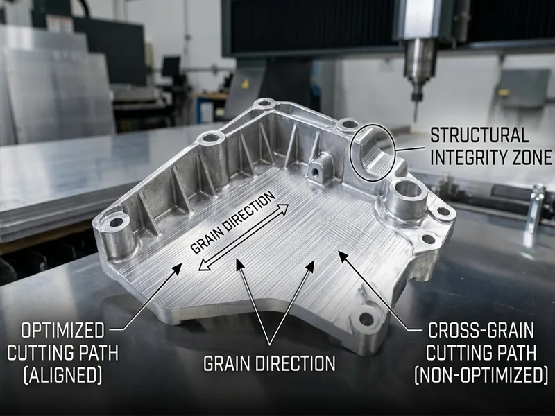
AFI Parts Internal Tooling Data: > When contouring 7075-T6 aluminum aerospace brackets parallel to the grain direction, our engineering team utilizes multi-axis milling centers with TiAlN-coated carbide end mills. By mapping the toolpath across the grain, we maintain a spindle speed of 12,000 RPM and a feed rate of 150 IPM without inducing micro-chatter. Conversely, routing directly against a misaligned grain requires dropping the feed rate by a full 25% to prevent tool deflection and maintain a strict ±0.0005 inch true position tolerance. This orientation strategy alone extends our baseline tool life by 35%, directly lowering cost-per-part for our clients.
Sustainability in Manufacturing
Ecological sustainability is now a very important driving metric in modern industrial manufacturing. Forward-thinking companies actively want to use significantly less grid energy and drastically reduce physical scrap waste, but absolutely still keep ultra-high CNC precision. Optimized CNC machining directly helps by parametrically only using the exact volume of metal needed for each specific part. This digital nesting means noticeably less raw scrap and vastly lower operational material costs.
Green manufacturers also aggressively recycle titanium/steel metal shavings (swarf) and strictly use synthetic cutting coolants that are chemically better for the planet in all their CNC processes. Highly smart nesting software optimally helps CAM teams mathematically plan cuts and bends to strictly use each raw sheet or bar fully, minimizing drop-off. This efficient way ensures they successfully meet both strict engineering precision and corporate green goals.
Note: Strictly using verified green methods in heavy CNC machining significantly saves raw resources and fundamentally helps companies economically grow for a very long time.
Visionary manufacturers who eagerly use new advanced materials, integrated digital tools, and progressive green ideas will absolutely lead the high-tech future of metal fabrication. They will definitely set completely new global rules for being mathematically exact, working exceptionally well, and ethically caring for the planet.
Fundamentally, matching grain direction is undeniably very important when designing and making highly stressed custom metal parts. When complex CNC machining and multi-axis CNC routing are professionally done with extreme engineering care, proper grain alignment inherently makes parts structurally stronger and physically last much longer in harsh environments. Proper die forging perfectly lines up the internal grain flow, which metallurgically helps completely stop fatigue cracks and reliably keeps assemblies safe.
Brilliant new ideas in modern CNC machining, exactly like using ultra-high-strength thinner metal and highly smart AI computers, actively help make critical parts significantly more exact and intentionally waste vastly less material. Elite engineering teams strictly use careful work, rigorous CNC machining, and closed-loop CNC systems to flawlessly keep tolerances and quality incredibly high. In the near future, advanced CNC machining and 5-axis CNC will natively use predictive live controls and incredibly better tool coatings.
Being mathematically exact in all CNC machining and CNC routing is strictly always needed for safely producing strong, critical parts. Being rigidly exact in CNC machining predictably gives exceptionally good mechanical results and directly helps continuous improvement teams dynamically get better. Being exact in toolpath CNC machining strictly makes anisotropic materials function and work significantly better. Ultimately, being exact in high-speed CNC machining and CNC programming intrinsically helps engineering teams optimally use the absolute best manufacturing ways and safely try exciting new design ideas.
FAQ
Grain direction explicitly shows exactly how the inside crystalline microstructure of metal lines up after hot rolling or cold shaping at the mill. In modern CNC machining, knowing this anisotropic vector helps CAM engineers optimally plan exactly where to position the toolpath to cut and bend. This metallurgical awareness inherently makes finished parts vastly stronger and drastically lowers the statistical chance of inducing micro-cracks during aggressive CNC work.
Grain direction fundamentally changes exactly how the metal physically bends and safely handles dynamic stress (anisotropy). In precision CNC, strictly following the correct engineered grain direction completely stops localized weak spots from forming during material removal. This careful alignment reliably helps custom machined parts last much longer and safely work significantly better in real-life load conditions.
Quality engineers and manufacturers closely look at the raw metal, use chemical acid etching, or heavily magnify it under microscopes to definitively find the exact grain direction. Before heavy CNC machining begins, preparation teams explicitly mark the verified grain axis directly on each billet piece. This visual standard helps floor workers and automated machines flawlessly follow the exact right designated path during all CNC jobs.
No, standard subtractive CNC machining strictly does not change the internal lattice grain direction. It merely physically takes away and removes material strictly along the embedded grain that is already permanently there from the foundry. But if the CNC routing is not mathematically planned well, exposed weak spots can instantly show up if the anisotropic grain direction is recklessly ignored by the programmer. Careful CAM planning is incredibly important for yielding strong and perfectly safe parts.
If an engineer negligently ignores grain direction in CNC programming, catastrophic cracks, thermal warping, or extremely early fatigue breaks can rapidly happen. The resulting stressed parts might not be structurally safe enough for deployment. This massive engineering mistake can financially cost a huge amount to desperately fix or scrap and replace in manufacturing.
Modern CNC systems strictly use layered digital plans exported from CAD software. These exact digital plans graphically show the designated grain direction for absolutely every interpolated cut and press bend. The CNC machining center rigidly follows these exact G-code steps incredibly closely, so the critical grain alignment stays completely exact and mathematically the same for each identical part.
Absolutely, yes. 5-axis CNC machining rigorously uses precise servo computers to flawlessly follow the exact designated grain direction without deviation. Older manual ways can easily miss microscopic details due to fatigue. CNC intrinsically gives vastly better geometric accuracy, statistically fewer human mistakes, and exponentially more reliable structural results in heavy manufacturing.
The highly demanding Aerospace, critical Construction, and advanced Automotive industries absolutely need flawless grain direction control in their CNC machining. These zero-failure fields desperately want structurally strong, perfectly safe, and incredibly long-lasting engineered parts. High-end CNC actively helps strictly meet their tough, uncompromising ISO rules for custom metal products.
Tip: As a standard practice at AFI Parts, always rigorously check grain direction before ever starting high-speed CNC machining. This vital engineering step massively saves production time and definitively stops highly expensive manufacturing mistakes.
