Introduction
Reducing the procurement cost of metal parts is never about chasing after small amounts of money at the stage of obtaining quotations—you do it by aligning design and sourcing from the start. This guide walks through seven practical moves that reduce total cost without sacrificing function: tune tolerances, cut setups, choose geometry and tooling that run fast and stable, pick materials and finishes that fit the job, and collaborate early with suppliers.
Throughout, we’ll anchor guidance to “suggested manufacturable ranges” and cite authoritative references so your teams can make confident calls. If your 2026 roadmap includes tighter timelines and leaner budgets, these tips support CNC machining cost reduction for 2026 engineering decisions you can defend in reviews.
Table of Contents
Design for manufacturability

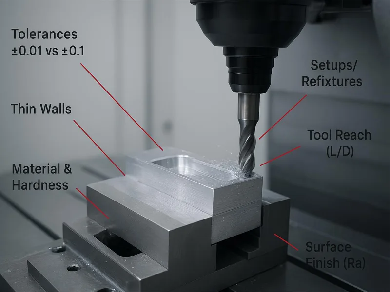
Tighten only what matters
Over‑constraining drawings slows machining, adds inspections, and lengthens lead time.
Start by mapping critical‑to‑function interfaces (mating fits, datum features, sealing surfaces) against non‑critical cosmetic geometry. Keep non‑critical geometry at general tolerances (e.g., ISO 2768‑m or shop default) and reserve GD&T for features that truly drive function. Typical practice: a bore-to-shaft fit may merit a positional or size tolerance near ±0.01 mm, while outer cosmetic faces can sit at ±0.10 mm.
Expect cost and cycle time to rise as tolerances tighten due to slower feeds, tool wear, and multi‑setup inspection; this tradeoff is widely noted by industry manufacturers—see the discussion on how tighter tolerances increase manufacturing complexity in Protolabs’ overview of manufacturing variations (2024) in the article “How to manufacture parts with manufacturing variations.” Link: According to the Protolabs blog article How to manufacture parts with manufacturing variations (2024), tighter tolerances increase complexity and cost: Protolabs — How to manufacture parts with manufacturing variations.
Two practical tips:
- Put a “tolerance map” on your drawing that highlights only the features that must be tight. Everything else defaults to general.
- Specify inspection levels by feature group so CMM time is spent where it matters.
Minimize setups and improve access
Every re‑fixture adds time, risk, and stack‑up error. Aim to expose as many features as possible in a single clamping by designing parts with clear tool access and stable datum schemes. Features that demand deep reach or awkward tool vectors often trigger extra setups, special holders, or slower toolpaths.
Design patterns that help:
- Use consistent primary datums so faces and holes align to one work coordinate.
- Favor open pockets and add generous internal radii so standard cutters can sweep corners.
- Consider 3+2 or 5‑axis friendly orientations to reduce re‑clamps when geometry is complex.
Workholding and access planning are well covered by trade sources; the general theme is consistent: simpler fixturing and fewer re‑fixtures reduce costs while improving repeatability.
Geometry and tooling choices
Respect thin-wall and pocket-depth limits

Thin walls and deep pockets are classic cost drivers due to chatter and deflection. Below are conservative “AFI 2026 recommended manufacturable ranges” you can use as a starting point. Adjust for wall height, part size, tolerance stringency, and machine/holder rigidity.
| Feature | Aluminum 6061/7075 | Mild/SS Steels | Titanium | Plastics (ABS/Acetal/PC) | Notes |
|---|---|---|---|---|---|
| Minimum wall thickness | 1.0–1.5 mm (short rib: 0.8–1.0 mm) | 1.5–2.0 mm | ≥2.0 mm | 2.5–3.0 mm | Consolidated from reputable design guides; suggested range, not a standard |
| Pocket depth limit (standard tools) | Target ≤3×D; up to 4×D | Target ≤3×D; up to 4×D | Target ≤3×D | Target ≤3×D | >4×D requires long‑reach/damped tooling and slower strategies |
| Tool overhang (L/D) | ≤3×D (std); 4×D with stiff holders; >4×D with damped systems | Same | Same | Same | OEM guidance supports damped adapters for higher L/D |
Why these numbers? Multiple industry design guides converge on keeping pocket depth to roughly 3–4× the tool diameter for stable, economical milling. For example, the Sogaworks CNC design guide (2024) summarizes that deeper pockets push you into long‑reach tools and slower strategies, which raises cost: Sogaworks — Design guide for CNC machining. For tool projection (L/D) beyond ~4×D, OEMs such as Sandvik recommend damped adapters; see Sandvik Coromant’s Silent Tools application guidance (2025): Sandvik Coromant — Silent Tools Application Guide.
Practical moves:
- Stiffen thin walls with ribs or increase thickness locally near clamp loads.
- Keep internal corner radii generous (ideally ≥ tool radius and, for deep features, target ≥1/3 of pocket depth) to allow faster toolpaths and longer tool life.
- If you must exceed 4×D pocket depth, plan for specialized holders, reduced stepdowns, and verification runs.
Standardize holes, threads, and radii
Standardization reduces custom tooling, setup variation, and inspection burden. Keep holes on standard drill sizes; align thread callouts to common ranges (metric M3–M12 or UNC/UNF equivalents) and avoid fractional oddities that require specials. For repeated assembly or soft substrates, specify helical inserts rather than over‑long thread engagement; most joints do not benefit beyond ~2× nominal diameter.
If your team needs a quick reference for recommended drill and tap sizes, keep a standard chart handy; AFI maintains a compact reference you can use during design reviews: AFI Parts — Drill and tap size charts. For general drawing best practices and when to combine counterbores/countersinks with standard holes, the Hubs technical drawing guide offers a helpful overview (2025): Hubs — How to prepare a technical drawing for CNC machining.
Materials and finishes

Choose machinable alloys with approved alternates
Pick materials that balance strength, machinability, availability, and finish compatibility. A few common, cost‑sensible pairings:
- Aluminum: 6061‑T6 is a versatile baseline with good machinability and wide availability; 7075‑T6 provides higher strength but can be more demanding and pricier.
- Stainless steels: 303 machines easier than 304 for non‑corrosive environments; use 316 when corrosion resistance is critical.
- Steels: 1018 or 12L14 are machinable for general use; 4140 pre‑hard is a good choice when wear resistance is needed without a separate hardening step.
Align alternates up front. In your RFQ, list an “approved alternates” column so procurement can pivot when supply tightens without re‑qualification delays. That single step can save days in 2026 supply swings.
Separate cosmetic and functional finishes
Treat appearance and performance as different requirements. Default to “as‑machined” on non‑cosmetic faces and specify a target roughness only where function demands it. Typical defaults place as‑machined around 3.2 µm Ra, with 1.6/0.8/0.4 µm successively finer—and costlier—finishes. Regional resources from digital manufacturers summarize these norms; see the Xometry overview (2024): Xometry — Selecting the right surface roughness for CNC machining.
When you need corrosion or wear performance, pick the thickness windows that match the job:
- Type II anodize for cosmetics/corrosion: about 5–25 µm (0.2–1.0 mil). For wear‑heavy applications, Type III hardcoat typically ranges 25–100 µm (1–4 mil). See the Aluminum Anodizers Council guideline (2024): Aluminum Anodizers Council — Guideline Hardcoat Anodizing.
- Electroless nickel provides uniform coverage, often specified between ~12.7–25 µm (0.0005–0.001 in) for general work, within a broader technical window up to ~127 µm depending on class. See Advanced Plating Tech’s process reference (2025): Advanced Plating Tech — Electroless Nickel Plating.
To keep costs predictable, separate “must‑meet” functional surfaces from “nice‑to‑have” cosmetics and give suppliers measurable acceptance (e.g., “Ra ≤ 1.6 µm on sealing lands only; bead‑blast cosmetic faces”).
Collaborate early for savings
Share volumes and invite DfM feedback
Early transparency lets your supplier right‑size processes, tooling, and inspection. Share:
- Volume bands (e.g., 10/100/1,000) to expose setup amortization and fixture ROI.
- A tolerance map highlighting critical features and inspection levels.
- Approved alternates for alloys and finishes, so quoting can proceed even if the first pick is constrained.
- Target surface roughness only where function demands it.
A short, well‑structured RFQ package typically yields faster, more comparable quotes and fewer change orders.
Brand insertion cue
As a neutral, real‑world example of early collaboration, AFI Industrial Co., Ltd. conducts an engineering review on new RFQs to flag geometry or tolerance risks before machining. In a recent anonymized case, the team identified a 0.8 mm unsupported wall on a tall pocket and proposed either a local rib or increasing the thickness to 1.2 mm with a larger internal radius. The customer accepted the change, which allowed standard tooling at ≤3×D depth and removed a planned re‑fixture. AFI then handled machining, a Type II anodize on cosmetic faces, and export packaging in one run, simplifying logistics.
If you need a single point of contact for review through delivery, see the overview of engineering support on the AFI site: AFI Parts — About and engineering support.
Conclusion
Apply these seven tips systematically, and you’ll cut the biggest drivers of cost while preserving function: tighten only what matters, design for fewer setups, respect thin‑wall and pocket‑depth limits, standardize holes/threads/radii, choose machinable alloys with pre‑agreed alternates, separate cosmetic from functional finish targets, and collaborate early with suppliers.
To accelerate quoting and reduce back‑and‑forth, document acceptable alternates, surface roughness targets by feature group, inspection levels, and batch plans directly in your RFQ package. That disciplined approach is a reliable path to CNC machining cost reduction for 2026 engineering decisions that deliver on time and on budget.
FAQ
Tightening tolerances unnecessarily increases manufacturing complexity, which directly leads to slower feeds, increased tool wear, and the need for multi-setup inspections. To keep costs down, you should map critical-to-function interfaces—such as sealing surfaces or mating fits—and only apply strict Geometric Dimensioning and Tolerancing (GD&T) to those specific areas. For example, a bore-to-shaft fit might require a ±0.01 mm tolerance, but non-critical cosmetic geometry should be kept at general tolerances like ISO 2768-m or ±0.10 mm.
Thin walls frequently drive up costs because they cause chatter and deflection during the machining process. Based on conservative manufacturable ranges, the recommended minimum wall thicknesses are:
- Aluminum (6061/7075): 1.0–1.5 mm, though short ribs can be 0.8–1.0 mm.
- Mild and Stainless Steels: 1.5–2.0 mm.
- Titanium: Greater than or equal to 2.0 mm.
- Plastics (ABS/Acetal/PC): 2.5–3.0 mm.
Multiple industry design guides recommend keeping pocket depths to roughly 3 to 4 times the tool diameter (3–4×D) to ensure stable and economical milling. If your design exceeds a 4×D pocket depth, it will require slower machining strategies and specialized equipment, such as long-reach tools or damped systems, which will increase the overall cost.
Standardization is an effective way to reduce the need for custom tooling, minimize setup variations, and lower the inspection burden. You can optimize your designs by keeping holes on standard drill sizes and aligning your thread callouts to common ranges, such as metric M3–M12 or their UNC/UNF equivalents. Furthermore, avoid specifying over-long thread engagements; most joints do not gain any structural benefit beyond approximately twice the nominal diameter.
To keep costs predictable, it is best to separate functional surface requirements from cosmetic appearance. You should default to an “as-machined” finish—typically around 3.2 µm Ra—for non-cosmetic faces, and only specify finer, costlier finishes (like 1.6, 0.8, or 0.4 µm Ra) exactly where the function demands it. When specifying coatings for performance, match the thickness to the job: use Type II anodize (5–25 µm) for cosmetics and general corrosion, and Type III hardcoat (25–100 µm) for wear-heavy applications.
