Introduction
If you’re here because your complex 5-axis CNC machined prototypes keep slipping schedule or blowing budget, you’re not looking for a textbook. You want a supplier who can machine the prototype quickly, control total cost, and hit the dimensions that matter—without endless back-and-forth.
That’s exactly what AFI Industrial Co., Ltd. (AFI Parts) is built for: fast, cost-controlled 5-axis CNC machined prototypes supported by engineering-led DFM review, practical workholding and setup strategy, CAM planning, and an inspection package sized to your drawing risk.
This article explains how we approach prototype builds so you can evaluate risk before release and know what to ask for in an RFQ. We’ll focus on the real schedule and cost drivers: DFM decisions that prevent rework, setup consolidation, toolpath choices that reduce cycle time, and inspection choices that avoid paying for data you don’t need.
Key Takeaway: For complex prototypes, the biggest schedule wins usually come from fewer setups, predictable datums, and an inspection plan that matches the drawing risk.
Table of Contents
DFM Foundations That Keep 5-axis Prototypes Fast and Cost-controlled
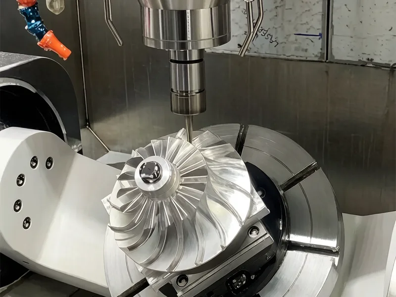
Geometry accessibility and stability
Before you ask for a 5-axis prototype quote, confirm the geometry behaves like a true multi-axis part and can be machined efficiently. This is one of the quickest ways to avoid a slow quote cycle, a slow first build, and an expensive second iteration.
Accessibility is the first gate. Deep features that require long tools drive chatter, tool deflection, and long cycle times. Internal sharp corners force small cutters and tiny stepovers, which increase finishing time. Thin webs and tall walls can be reachable but unstable; they may need rest machining sequences, support tabs, or a staged rough/finish plan to control distortion.
A fast DFM review should answer three questions:
- Can the critical surfaces be reached with a reasonable tool length? If the only path is a long stickout, the shop will slow feed and add spring passes. Expect more variation.
- Can you keep a stable datum scheme through machining and inspection? If the drawing’s primary datum is on a face that gets finished last, you’ve created a measurement argument.
- Does the part have a safe roughing plan? Some freeform parts look simple but hide thin sections that collapse when you remove stock.
At AFI Parts, our DFM reviews for complex prototypes typically start with collision and reach checks in CAM simulation and a risk list tied back to drawing features. When we flag risks early, the fix is often a small design edit (a slightly larger internal radius, a changed datum priority, or an extra stock allowance on a thin wall) that prevents multiple rework loops later. If you’re deciding whether 5-axis is the right process, AFI’s overview of 5-axis machining capabilities is a useful baseline.
GD&T and drawing decisions that prevent quote and build delays
For prototypes, GD&T should protect function, not punish process. The practical goal is to keep everyone aligned on what must be correct on iteration one, and what can be confirmed with lighter verification.
Three drawing issues account for a lot of schedule churn:
- Over-specified freeform surfaces: Tight profile tolerances across broad, blended geometry often translate into longer finishing cycles and longer CMM time. If only a few interfaces drive function, it’s usually faster to tighten those and relax non-functional areas.
- Unstable or inconsistent datum logic: When datum priority changes between views (or datum targets are unclear), the supplier may build to one interpretation while inspection aligns to another.
- Unstated inspection expectations: If the drawing is silent but the buyer expects a full FAI-style package, you often discover that mismatch late.
What typically helps an RFQ move faster is a short, explicit “prototype intent” layer:
- Identify CTQs (critical-to-quality features) and how you expect them to be verified (CMM, pin gage, height gage, on-machine probing).
- Specify surface finish only where it affects function (seals, bearings, optical interfaces), and keep the rest process-typical.
- State inspection deliverables up front: a feature-focused CMM report, a broader dimensional report, or a formal FAI framework (many aerospace programs use AS9102 for Forms 1–3).
This isn’t about doing less quality work. It’s about buying the right amount of verification for a prototype, then scaling inspection as the design stabilizes.
Material-driven capability and finish

Material choice affects cycle time, finish options, and how hard it is to measure the part.
For example, aluminum prototypes are often selected for speed, but the exact alloy and finish still matter. If you need hard anodize (Type III), the build-up can shift critical fits and should be planned in the nominal dimensions and inspection plan. Stainless and titanium bring more heat into the cut; without conservative toolpaths and wear monitoring, they can drift over a run.
A material-driven DFM review should confirm:
- Capability vs. tolerance stack: if you need sub-thou features, specify where they are truly required and how they will be verified.
- Finish vs. function: bead blast improves visual uniformity but can change edges and small features.
- Test coupons/witness samples when special processes matter.
If you want a single reference point for supplier capability and typical tolerance bands, start with the AFI Parts CNC milling capability page and align your drawing tolerances to the process plan, not the other way around. For tolerance-cost tradeoffs, AFI also publishes a practical guide on CNC machining tolerances.
How AFI Parts Runs a Fast Prototype Build
To keep a prototype moving, you need a process that produces answers early—before metal is cut—and avoids “surprises” that appear only after finishing.
Here’s the practical workflow AFI Parts uses for complex 5-axis CNC machined prototypes:
1) Engineering-led DFM, focused on iteration speed
We start by identifying the few features that actually control function (fits, sealing faces, bearing bores, alignment surfaces). Then we map the risks that create delays: tool reach, thin-wall distortion, datum stability across operations, and finish-induced dimension shifts.
The output is a short DFM note set. It’s not a lecture. It’s a list of decisions and options.
2) Setup strategy first, CAM second
For complex parts, CAM time is often wasted if the setup plan isn’t locked. We decide how the part will be held, what the probing/zero strategy is, and which surfaces are finished in which orientation.
This is also where we decide whether the fastest path is:
- one consolidated 5-axis setup,
- a 5-axis + 3-axis split, or
- a staged approach that keeps the part stable during roughing before final finishing.
3) Toolpath plan that targets cycle time without creating rework
Cycle time doesn’t matter if it produces scrap. We prefer roughing strategies that keep engagement stable and finishing strategies that reduce passes while preserving surface and geometry control.
When a circle-segment tool is appropriate, we validate cusp height and tilt limits in simulation. When it isn’t, we don’t force it.
4) Inspection plan sized to drawing risk
A prototype doesn’t always need an aerospace-style inspection package. What it does need is clarity.
We align early on what will be measured, how it will be reported, and what “good enough” means for non-critical cosmetic areas. That reduces delays caused by inspection scope creep.
5) Shipping and documentation are treated as part of the lead time
For global programs, packaging, paperwork, and shipping method can be the difference between “on time” and “missed it.” We plan those steps alongside machining so they don’t become last-minute schedule surprises.
Toolpaths and Tooling that Compress Cycle Time
Adaptive roughing and high-feed tactics
Roughing strategy sets your ceiling on lead time.
Adaptive roughing (often implemented as trochoidal-style tool motion) keeps the tool load more constant than conventional pocketing. That typically allows higher average feed rates and reduces tool abuse in corners.
As a starting point, Metalcam’s write-up on “advantages of adaptive roughing” (2025) notes time reductions up to about 50% in some cases. Treat that as a “possible upside” range, not a quote guarantee. Real results depend on engagement limits, tool diameter, stickout, and whether the machine can maintain feed.
High-feed tactics in 5-axis prototypes often show up as:
- high-feed roughing on open faces with stable engagement
- rest-roughing that avoids air cutting
- avoiding deep axial cuts on thin features that will move
The practical aim is simple: remove stock fast without creating distortion, you’ll have to chase in finishing.
Multi-axis finishing (swarf, morph, steep-and-shallow)
Finishing time is where complex prototypes quietly become expensive.
Multi-axis finishing strategies exist to keep tool contact stable and reduce passes:
- Swarf can finish ruled surfaces with the tool’s side, which is efficient when geometry supports it.
- Morph/flowline strategies help maintain consistent scallop height across blended surfaces.
- Steep-and-shallow splits finishing by surface slope, so you’re not forcing one toolpath type to do everything poorly.
A disciplined finishing plan also reduces inspection burden. If surface finish varies wildly across the part, your CMM or scan strategy gets harder to interpret.
If you’re aligning supplier selection around program risk (not just quoted hours), ask for machine-aware simulation screenshots or collision reports as part of the build package. That’s one place AFI Parts uses CAM simulation to de-risk complex tool tilt and avoid surprises late in the cycle.
Circle-segment cutters vs ball endmills

Ball endmills are the default for 3D finishing, but they’re rarely the fastest option on broad freeform surfaces.
The reason is geometry. A ball endmill has a fixed tool radius. The smaller the allowed scallop (cusp) height, the smaller your stepover must be, which means many finishing passes. A simplified relationship often used for scallop height is:
- cusp height (h) grows with the square of stepover (a_e)
- and decreases with tool radius (r)
CNC Cookbook’s guidance on choosing stepover for 3D profiling (updated 2026) explains how scallop height targets map to stepover choices.
Circle-segment cutters (often called barrel or lens tools) change the equation. Instead of finishing with the ball tip, they present a much larger effective radius along the side profile. ISCAR’s technical article “Barrel cutter shapes a new milling trend” (2018) notes that the distance between passes can be increased at least five times without degrading surface finish parameters in suitable geometries.
That’s the cycle-time lever: larger stepover at the same cusp height.
AFI Parts’ practical approach to circle-segment tools is conservative and validation-driven:
- Tool selection: choose barrel/lens radius based on surface curvature so the tool can maintain contact without gouging. If curvature is tight, we still use ball endmills or smaller radii.
- CAM simulation: validate cusp height targets and tool tilt limits in CAM. We treat the simulation as a first-pass filter, not proof.
- Sample inspection: measure a small set of representative surface features on the first article (profile or sectional scans where required). If the measured deviation or surface finish is off, we adjust stepover, tool tilt, or switch to a different tool form.
For engineers, the supplier-facing question is: “How do you pick the barrel radius, and how do you verify cusp height?” If the answer is only “CAM says it’s fine,” expect iteration.
Verification and Closed-loop Quality
In-process probing and wear compensation
In-process probing can do two important jobs on prototypes: establish the work coordinate system quickly, and catch drift before you finish a part that will fail.
Probing isn’t magic. It needs a plan: what features will be probed, what tolerance bands trigger action, and how tool wear offsets are updated. For prototypes, the simplest closed-loop approach is often enough: probe critical datums after roughing, probe a key bore or plane before finishing, then compensate wear or thermal drift with controlled offset updates.
CMM, FAI, and traceability packages
| Inspection approach | Best when you need | What it typically includes | Common tradeoff |
|---|---|---|---|
| CTQ-focused dimensional report | Fast prototype decisions on a few functional interfaces | Measurements on the specific bores, planes, positions, and profiles that drive fit/function | You may not get full-part coverage on cosmetic/non-functional geometry |
| Standard dimensional report with CMM + key manual checks | Broader confidence on a complex part without full FAI paperwork | A wider measurement set, plus documented tools/standards used | More inspection time than CTQ-only; still not a formal FAIR package |
| FAI framework aligned to AS9102 | Aerospace-style traceability and customer-required documentation | Ballooned characteristics + recorded actuals + material/process accountability | Highest time cost; can become the lead-time driver if the scope isn’t controlled |
| Deviation map/scan for freeform surfaces | You need to understand surface form, not just discrete points | Point cloud or deviation plot tied to datums | Data is richer, but can be slower to generate and interpret |
If you want predictable quality from a new supplier, ask for the deliverables up front.
For aerospace-style control, AS9102 is a common framework for first article inspection. It requires structured reporting and traceability: ballooned drawing characteristics, recorded actual measurements (not just pass/fail), and material/process accountability. See InsideMetalFab’s “First Article Inspection in CNC Machining” (2026) and Fictiv’s FAI manufacturing guide (2025) for the practical workflow and common triggers.
For complex 5-axis surfaces, a CMM report that includes deviation mapping or point clouds can be more informative than a sparse set of points. Quality Magazine’s article on “Utilizing CMM data” (2020) discusses integrating CMM results into ballooned inspection reports to reduce manual transfer error.
At AFI Parts, the standard approach is to align inspection with what the drawing is really trying to control: critical datums and functional interfaces get the densest verification; non-critical cosmetic surfaces are measured enough to confirm the process is stable.
Feedback to offsets and thermal control
The most expensive quality problems in prototyping are the ones you find late.
Closed-loop quality means you have a mechanism to respond: feed measured deviation back into tool wear offsets, fixture corrections, or program updates. It also means controlling temperature effects where they matter. Long finishing cycles on aluminum or stainless can create heat-related drift that shows up as a profile shift or a bore moving out of position.
A simple practice that prevents repeat failures is revision discipline: every program change should be traceable to a feature and a measurement result, and you should know whether a partial FAI is needed for affected characteristics. When NC programming changes affect only some dimensions, partial FAI is commonly used to verify the changed characteristics rather than repeating the full inspection package.
Lead Time and Total Cost Levers for NPI
Machine-aware simulation and CAM templates

When prototype schedules slip, it’s often because each iteration is treated like a one-off.
Machine-aware simulation helps prevent two avoidable delays: collisions discovered on the machine and tool reach problems discovered after the part is already half-finished. Even for a one-piece prototype, asking for collision checks and a documented setup plan is a program control, not a luxury.
CAM templates matter for repeatability. If your supplier has standard approaches to:
- probing cycles and datum pick-up
- tool libraries by material
- rough/finish templates by feature class
…you get fewer surprises and a more predictable cycle time.
Itemized quotes and a hidden cost checklist
The goal of an RFQ is not to get a number. It’s to prevent cost and schedule surprises.
For complex 5-axis CNC prototyping, ask for an itemized quote that separates:
- programming (CAM) time
- setup and fixture time
- roughing vs finishing cycle time
- inspection scope (what is measured, and how it’s reported)
- material and finish costs
- special process certifications and documentation
This is also where you flush out hidden cost drivers: extra setups, custom fixtures, rework allowances, expedited freight, or inspections that exceed what you intended.
Pro Tip: If a supplier won’t separate setup, programming, and inspection in the quote, treat the lead time as higher risk. Those are the three buckets that usually move.
Logistics, certification, and risk buffers
Prototype schedules fail at the edges: shipping, cert packages, and revision churn.
If you are sourcing globally, build in time for:
- documentation review (material test reports, finish certs, FAIR format)
- packaging requirements for delicate surfaces
- customs and freight variability
Also, plan a buffer for engineering changes. Your first iteration is rarely your last.
If you need a supplier that can support both fast prototypes and the eventual production handoff, start by confirming capabilities and documentation expectations. AFI Parts’ metal cutting overview page is a useful internal reference for aligning process scope with program needs.
What You Should Receive Back From a Serious Prototype Supplier
A fast prototype program isn’t just about machining time. It’s about getting clear answers you can use for the next design decision.
For complex 5-axis CNC prototypes, it’s reasonable to expect a supplier to return (at a minimum) the items below. They make the schedule more predictable and reduce the chance of paying for avoidable rework:
- A short DFM note set that flags reach, distortion, datum stability, and finish-related risks (with options, not just warnings)
- A setup and datum strategy summary (even a simple written description) so machining and inspection align
- An itemized quote that separates programming, setup/fixture effort, machining time, and inspection scope
- An inspection plan that states what will be measured, how it will be reported, and what standards apply if formal documentation is required
- A revision/changes approach that clarifies what gets re-verified after a program or design change
When you see these elements in writing, you can compare suppliers on risk—not just on a single number.
Conclusion
Cutting time and cost on complex 5-axis prototypes isn’t about asking for a heroic lead time. It’s about preventing the rework loops that quietly add days: unstable datums, extra setups, slow finishing strategies, and inspection scopes that don’t match functional risk.
AFI Parts supports faster iterations by pairing engineering-led DFM with a practical setup plan, cycle-time-aware toolpaths, and an inspection approach that’s explicit and proportional to the drawing.
If you’d like a DFM review and an itemized quote for a complex 5-axis prototype, you can contact AFI Parts with your CAD/drawing package and the few requirements that matter most (material, finish, CTQs, and desired inspection deliverables).
FAQ
Reduce iteration loops: send a complete RFQ package (CAD + drawing + CTQs), choose stable datums, avoid long-reach tooling where possible, consolidate setups, and align inspection scope to functional risk (not full-part perfection).
Send STEP + PDF (with revision), material and finish requirements, quantities, target deadline/shipping destination, your CTQs (ballooned or noted), and what inspection deliverables you need (CTQ CMM report vs standard report vs AS9102-style FAI).
When the part is mostly prismatic (3+2 can be faster), when inspection alignment becomes unclear in tilted orientations, when finish build-up dominates fit (anodize/plating decisions matter more), or when the design should be split into simpler parts for stability and cost.
