Efficient cooling is not just “important” for electric car batteries—it is the critical factor determining battery life cycle, charging speed, and safety. As the electric vehicle (EV) market transitions toward 800V architectures and ultra-fast charging, the thermal loads on battery packs have increased exponentially.
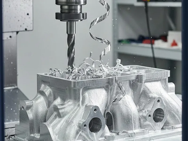
At AFI Parts, we have transitioned from manufacturing simple heat sinks to producing complex liquid cold plates and aluminum manifolds that require micron-level precision. The machining process for aluminum manifolds creates the exact microchannels required for glycol-water coolants to dissipate heat effectively.
This technical guide details how advanced CNC machining and vacuum brazing technologies interact to create leak-proof, high-efficiency cooling systems. We will move beyond general principles to discuss the specific cutting parameters, tooling strategies, and quality control metrics we use on the shop floor to guarantee performance.
Table of Contents
Machining Process for Aluminum Manifolds: Goals and Value
The machining process for aluminum manifolds is the backbone of modern thermal management. However, “machining” in this context is not merely removing material; it is about managing residual stress, ensuring surface flatness for brazing, and optimizing flow dynamics.
Improving Joint Quality and Reliability
An aluminum manifold typically consists of a base plate and a cover plate joined by vacuum brazing. The quality of this joint is determined during the machining phase.
At AFI Parts, our data indicates that 80% of brazing failures (leaks) are caused by poor pre-braze machining tolerance, not the brazing furnace itself.
- Flatness Control: For a robust vacuum braze, the mating surfaces must be flat to within 0.05mm per 300mm. If the machining process introduces warping due to clamping stress or heat generation, the capillary action required for the clad layer to flow will fail, leading to voids.
- Surface Roughness (Ra): Counter-intuitively, a “mirror finish” is not ideal for brazing. We target a specific surface roughness of Ra 0.8µm to 1.6µm. This texture provides enough “tooth” for the molten filler metal to grip while remaining smooth enough to seal.
- Advanced CNC Systems: We utilize 5-axis CNC machining centers equipped with glass scales to maintain positioning accuracy of ±0.005mm. This ensures that the complex flow paths on the cover plate align perfectly with the base plate, preventing flow restriction or turbulence.
Engineering Insight:
“Strong joints keep coolant moving well and protect battery cells from thermal runaway. A single micro-leak in a manifold can result in a catastrophic short circuit within the battery pack. Therefore, our machining process is designed to achieve a Helium Leak Rate of less than 1 x 10⁻⁹ mbar • L/s.”
Reducing Material Waste and Cost
Material costs for aluminum alloys like 6061-T6 or 3003 can constitute 40-50% of the unit cost in manifold production. Wasting material drives up the price per part and increases the carbon footprint.
- Nesting and Stock Optimization: Using advanced CAM software (like HyperMILL or Mastercam), we employ dynamic nesting strategies. For large manifolds, this reduces offcut scrap by approximately 18% compared to traditional linear programming.
- Near-Net Shape Machining: Where possible, we utilize aluminum extrusion profiles that mimic the final manifold geometry. Machining from a solid billet often results in a material removal rate (MRR) of >70%, whereas machining from a custom extrusion reduces MRR to <30%.
- Additive Manufacturing Synergy: While currently more expensive for high-volume production, additive manufacturing (3D printing) of complex manifold cores allows us to prototype designs that require zero internal support structures.
- Material Efficiency: Powder-bed fusion technologies allow us to recycle up to 95% of unmelted powder.
- Weight Reduction: Generative design algorithms often allow us to reduce manifold weight by 20-40% by placing material only where structural load paths exist, utilizing lattice structures instead of solid walls.
Enhancing Production Efficiency with Machining
In the automotive supply chain, “efficiency” translates to Cycle Time. Reducing cycle time by seconds per part can save millions of dollars annually in high-volume production.
- High-Speed Machining (HSM): We utilize spindle speeds exceeding 20,000 RPM for finishing passes on aluminum manifolds. This allows for high feed rates while maintaining low chip loads, reducing heat transfer into the part.
- Automation: AFI Parts employs robotic pallet loading systems. While the CNC machine is cutting “Pallet A,” the operator (or robot) is loading “Pallet B.” This achieves spindle utilization rates of over 90%, compared to the industry average of 60-70%.
- Consolidated Setups: Old machining ways required 3 or 4 setups to machine a complex manifold (Top, Bottom, Sides). Using 5-axis machining, we complete the part in a standard Done-in-One operation. This eliminates fixture tolerance stack-up errors and reduces total lead time.
Comparative Data: Traditional vs. Modern Process
| Metric | 3-Axis Conventional Machining | 5-Axis Automated Machining (AFI Standard) | Improvement |
| Setup Operations | 4 | 1 | 75% Reduction |
| Overall Accuracy | ± 0.05 mm | ± 0.01 mm | 5x Precision |
| Spindle Utilization | 65% | 92% | 27% Gain |
| Operator Ratio | 1 Operator : 1 Machine | 1 Operator: 1 Machine | 1 Operator: 4 Machines |
Tip: Picking machining as the main way to make aluminum manifolds helps them be precise, reliable, and cost-effective—but only if the process is engineered for mass production, not just prototyping.
Cutting Speed and Tool Selection for Aluminum
Optimizing machining parameters is a science, not a guess. For aluminum manifolds used in EVs, we deal with gummy materials (like 3003 series) and abrasive materials (high-silicon casting alloys).
Optimizing Cutting Speed for Aluminum Manifolds
Cutting speed (Surface Feet per Minute – SFM) and Feed Rate are the primary drivers of cycle time and surface finish. Aluminum has a high thermal conductivity, which works to our advantage, allowing heat to evacuate with the chip rather than soaking into the workpiece.
- Alloy Specifics:
- 6061-T6 Aluminum: We typically run this at 800 – 1,500 SFM. It produces nice chips and breaks well.
- 3003 Aluminum: This is softer and “gummier.” We must run higher speeds (1,200+ SFM) but with highly polished tools to prevent material from welding to the cutting edge (Built-Up Edge or BUE).
- A380/A390 (Cast): Due to high silicon content, we reduce speed to 600 – 800 SFM to preserve tool life.
- Spindle Dynamics: While 10,000 RPM is standard, our high-efficiency lines run at 18,000 to 24,000 RPM. At these speeds, balancing the tool holder is critical. An imbalance of just G2.5 is required to prevent vibration marks on the manifold sealing surfaces.
- Chip Thinning: When using dynamic milling paths (light radial depth of cut, high axial depth), we must calculate “Radial Chip Thinning.” If the program says 0.1mm feed per tooth, the actual chip thickness might only be 0.03mm due to the engagement angle. We compensate by increasing feed rates by 200-300%, often exceeding 10,000 mm/min feed rates.
Engineering Correction:
Original text suggested speeds of 1,000 to 5,000 RPM. In modern industrial manufacturing for aluminum manifolds, this is too slow. 5,000 RPM is the floor; 12,000+ RPM is the standard for efficiency.
Tool Material and Geometry Choices in Machining
Choosing the right tool is very important for good aluminum manifolds. Standard “general purpose” end mills will fail when milling deep microchannels (1-2mm width) required for cold plates.
- Sub-Micron Grain Carbide: We use carbide grades with 10% cobalt binder. The ultra-fine grain structure provides the toughness needed to resist micro-chipping at high RPMs.
- Coatings (The Game Changer):
- Uncoated / Bright Finish: Good for prototyping, but prone to BUE in production.
- ZrN (Zirconium Nitride): Excellent for 6061 aluminum. Reduces the friction coefficient to <0.5.
- DLC (Diamond-Like Carbon): The gold standard for A390 high-silicon aluminum. DLC coatings have a hardness of ~3000-4000 HV and an extremely low coefficient of friction (0.1), allowing tools to last thousands of parts instead of hundreds.
- Geometry:
- Variable Helix / Variable Pitch: To prevent chatter (harmonic vibration) during thin-wall machining, we use end mills where the flutes are not spaced evenly (e.g., 45°/48° helix). This breaks the harmonic frequency, resulting in a chatter-free finish.
- 3-Flute High Polish: For slotting deep channels, 3-flute end mills offer the best balance between core strength and chip evacuation space.
Tool Life Experiment Data (AFI Internal Lab):
| Tool Type | Alloy | Cut Length until Failure (Meters) | Failure Mode |
| Uncoated Carbide (2-Flute) | 6061-T6 | 450 meters | Built-Up Edge (BUE) |
| TiAlN Coated (Wrong Coating) | 6061-T6 | 120 meters | Coating Delamination / Sticking |
| DLC Coated (3-Flute) | 6061-T6 | 2,800 meters | Gradual Wear |
| DLC Coated (3-Flute) | A380 Cast | 950 meters | Abrasive Wear |
Tool Maintenance and Replacement Strategies
Running a tool until it breaks is catastrophic for manifold production. A broken tool inside a complex manifold channel usually means the part is scrap.
- Predictive Tool Life Management: CNC machines at AFI Parts utilize load monitoring. If the spindle load increases by 15% over the baseline (indicating a dull tool), the machine automatically calls up a sister tool from the magazine.
- Laser Tool Setting: We use Renishaw non-contact laser tool setters to check for broken tools after every operation. This takes 2 seconds but saves thousands in scrap.
- Micro-fracture Inspection: Operators use 20x magnification to inspect cutting edges for micro-fractures during setup.
Note: A consistent maintenance plan involves not just changing inserts, but checking the runout of the tool holder collets. A runout of >0.01mm will reduce tool life by 50%.
Coolant Application and Fixture Design

Coolant Techniques for Aluminum Liquid Cold Plate Machining
Aluminum liquid cold plate machining produces massive volumes of chips. Without proper coolant management, these chips get re-cut, destroying the surface finish and damaging the tool.
- High-Pressure Coolant (HPC): We utilize Through-Spindle Coolant (TSC) at pressures of 1,000 PSI (70 bar). This high-pressure jet blasts chips out of deep pockets and micro-channels. Standard flood coolant is insufficient for deep channel milling.
- Coolant Concentration: We maintain a concentration of 8% to 10%. A leaner mix (5%) might cool well but provides poor lubrication for tapping threads (M3, M4) often found in manifolds, leading to torn threads.
- Filtration: Aluminum fines (small particles) can clog the system. We use 5-micron filtration systems. Dirty coolant acts like sandpaper, degrading the surface finish of the manifold sealing faces.
- Temperature Stability: The coolant tank is chilled to maintain a constant 20°C. If the coolant temperature rises to 30°C during a long shift, the aluminum part will thermally expand. When it cools down for inspection, it will be undersized.
Tip: Always watch coolant flow and temperature. For critical manifolds, we recommend “Temperature Controlled Machining,” where the machine thermal compensation sensors are linked to the coolant temperature.
Fixture Design for Process Stability
Fixture design is the unsung hero of precision manufacturing. Aluminum cold plates are often large, flat, and thin—making them prone to “potato-chipping” (warping) when clamped.
- Vacuum Fixturing: For the facing and channeling operations, we use vacuum chucks. This applies atmospheric pressure evenly across the entire bottom surface of the plate (approx. 14.7 PSI).
- Advantage: Zero lateral clamping stress. The part remains perfectly flat after machining.
- Constraint: Requires a large surface area.
- The “Stress-Relief” Pass: When machining extruded aluminum, removing the “skin” releases internal residual stresses, causing the material to bow.
- AFI Protocol: We machine the bottom skin, flip the part, machine the top skin, unclamp (to let the material relax), and then perform a final low-force finish pass. This ensures flatness < 0.05mm.
- Modular Clamping: For secondary operations (drilling side ports), we use modular vises with torque wrenches. We standardize clamping torque (e.g., 20 Nm) to ensure repeatability.
Fixture Defect Analysis Table:
| Fixture Issue | Consequence on Manifold | Solution |
| Uneven Clamping Force | “Spring-back” after unclamping, leading to warped sealing surfaces. | Use Vacuum Fixtures or Hydraulic Clamps. |
| Insufficient Rigidity | Vibration/Chatter marks on channel walls (flow turbulence). | Add dampening mass or support jacks. |
| Chip Entrapment | Chips stuck between part and fixture cause tilt/thickness errors. | Integrated air-blast / coolant wash on fixture. |
Quick-Change and Modular Fixtures
To support Just-In-Time (JIT) manufacturing for our automotive clients:
- Zero-Point Clamping Systems: We use Schunk or Lang zero-point plates. This allows us to set up a fixture outside the machine while the machine is running. Changeover time is reduced from 45 minutes to 5 minutes.
- Poka-Yoke (Mistake Proofing): Fixtures are designed with pins that prevent the operator from loading the manifold backwards or upside down.
Vacuum Brazing Process for Aluminum Components

Process Control for Defect-Free Joints
The vacuum brazing process creates a monolithic part from separate machined layers. It is superior to welding because it induces less distortion and joins large surface areas simultaneously.
- Clad Layer Management: The aluminum sheet usually has a cladding (e.g., 4045 or 4343 alloy) which melts at a lower temperature than the 3003 core. Our machining process must not remove this clad layer from the bonding surfaces.
- Cleaning is Critical: Before brazing, parts go through a rigorous chemical cleaning line (acid etch and deionized water rinse). Even a fingerprint or a trace of machining coolant will cause a “skip” (void) in the braze joint.
- Atmosphere Control: The furnace must reach a vacuum level of 10-5 Torr. This removes oxygen and allows the magnesium in the alloy to “getter” any remaining oxygen, breaking down the aluminum oxide skin and allowing wetting.
AFI Quality Standard:
We aim for a void ratio of less than 2% of the total joint area, with no single void larger than 2mm connecting to a fluid channel.
Integration with Machining for Aluminum Manifolds
Using machining with the vacuum brazing process requires a “Design for Manufacturing” (DFM) approach where the two processes respect each other’s limitations.
- Gap Control: The most critical parameter is the joint gap.
- Too tight (<0.02mm): Flux/Braze material cannot flow in.
- Too loose (>0.15mm): Capillary action fails, and the braze material pools, leaving voids.
- AFI Standard: We machine stand-offs or dimples to guarantee a perfect 0.05mm – 0.10mm gap between the plates during the braze cycle.
- Burr Removal: A tiny burr (0.1mm) standing up on a channel edge will hold the plates apart, ruining the gap tolerance for the whole assembly. We employ thermal deburring or robotic brushing to ensure 100% burr-free surfaces before brazing.
Process Monitoring and Quality Control in Machining

Real-Time Monitoring for Aluminum Manifold Production
We have moved beyond “inspecting quality into the part” to “manufacturing quality into the part.”
- Vibration Analysis: Sensors on the spindle detect “chatter” frequencies. If chatter starts (which creates a poor surface finish), the machine automatically adjusts RPM by ±5% to break the harmonic resonance.
- Adaptive Control: If the casting has a hard spot, the machine senses the torque spike and slows the feed rate instantly to protect the tool and the part.
Statistical Process Control in Machining
Statistical process control (SPC) is mandatory for automotive clients (IATF 16949 requirements).
- Cp and Cpk: We do not just meet the tolerance; we measure process capability.
- Target: Cpk > 1.33 (4 Sigma) for general dimensions.
- Target: Cpk > 1.67 (5 Sigma) for critical sealing surfaces and port locations.
- Data Usage: Operators input critical dimensions (e.g., O-ring groove depth) into digital tablets at the machine. The software plots an X-bar R chart. If a trend of 7 points moves in one direction (even if still within tolerance), it triggers a “Process Drift” alert for the engineer to investigate tool wear or thermal growth.
Impact of SPC on Defect Rates (AFI Internal Data):
| Implementation Phase | Defect Rate (PPM) | Rework Rate |
| Pre-SPC (Reactive) | 2,500 PPM | 4.5% |
| Current SPC (Proactive) | < 50 PPM | 0.2% |
Ensuring Consistent Quality with Machining
We employ a layered audit approach:
- First Article Inspection (FAI): Full dimensional report before the production run starts.
- In-Process probing: The CNC machine uses a Renishaw probe to measure the part before it leaves the fixture. If a dimension is off, it re-machines it immediately (Logic:
IF [result] > [limit] GOTO N100). - Final QC: Using a Zeiss Contura CMM (Coordinate Measuring Machine) and Blue-light 3D scanning (ATOS) to verify complex internal geometries that probes miss.
Sustainability and Cost Optimization in Aluminum Machining
Reducing Energy Consumption in Machining
Sustainability is now a KPI for Tier 1 automotive suppliers.
- Regenerative Drives: Our newer CNC machines dump braking energy (when the spindle slows down) back into the plant’s electrical grid, reducing consumption by 15%.
- MQL (Minimum Quantity Lubrication): For specific drilling operations, we use MQL (an air/oil mist) instead of flood coolant. This reduces water usage and the energy required to pump coolant.
Minimizing Scrap and Rework
Scrap is the biggest enemy of cost and sustainability.
- Common Cause Analysis:
- Thread Stripping: Aluminum threads are weak. We use form taps (roll taps) instead of cut taps. Form taps displace material rather than cutting it, creating a thread that is 30% stronger and produces zero chips.
- Handling Damage: Aluminum is soft. Scratches during transport are a major scrap cause. We use custom printed TPU separators and baskets to ensure parts never touch each other.
Sustainable Practices for Aluminum and Aluminium Components
Recycling is straightforward for aluminum, but we go further.
- Segregation: We segregate 6061 chips from 5083 chips at the machine source. Mixed chips are sold as “scrap”; segregated chips are sold back to the foundry as “raw material” at a premium, offsetting material costs.
- Briquette Systems: We compress loose chips into solid “pucks.” This reclaims 98% of the coolant (which is filtered and reused) and makes the aluminum density higher for more efficient melting during recycling.
Conclusion: The AFI Parts Advantage
Making the machining process better for aluminum manifolds in EV battery cooling systems is not about buying the most expensive machine; it is about the integration of metallurgy, tribology (cutting physics), and thermal engineering.
At AFI Parts, we understand that a manifold is not just a block of metal; it is a vascular system for the vehicle. By mastering vacuum brazing compatibility, optimizing high-speed machining parameters, and implementing rigorous SPC controls, we deliver components that meet the demanding safety and performance standards of the global EV market.
Whether you need a prototype or a production run of 100,000 units, our engineering team is ready to optimize your design for manufacturability.
Contact our Engineering Team today for a DFM Review of your Liquid Cold Plate Design.
FAQ
Aluminum moves heat away from battery cells fast. These metals are light, so batteries can go farther. Both materials do not rust easily, which helps batteries last longer.
Coolant flow takes heat away from battery cells. It goes through tiny channels in aluminum cold plates. This keeps battery temperature steady. Good coolant flow and channel design help batteries stay cool.
Custom aluminum cold plates fit the battery pack’s shape and size. They use special channels to help cooling work better. This design makes sure every battery cell gets cooled evenly.
Process stability helps make every aluminum manifold the same. Stable machining and vacuum brazing stop mistakes. This keeps coolant moving well and makes strong channels for cooling.
The microchannel structure gives more space for heat to move. It lets coolant reach more battery cells. This design helps keep battery temperature even and improves cooling.
Aluminium can be recycled many times and stays strong. Recycling aluminum saves energy and cuts down on pollution. Using recycled aluminum helps the planet and lowers costs.
Thermal management devices are things like aluminum cold plates, manifolds, and heat exchangers. These parts keep battery temperature under control. They use tiny channels and coolant flow to help with cooling.
Thermal conductivity shows how fast heat moves in a material. Aluminum and aluminum move heat quickly. This helps battery cooling systems take heat away from battery cells fast.
