
Key Takeaways:
- Material Selection: C11000 ETP (Electrolytic Tough Pitch) Copper per ASTM B187 offers 100% IACS electrical conductivity (58.0 MS/m) and superior thermal dissipation, making it the preferred choice for high-current electrical busbars.
- CNC Punching Precision: Maintaining punch-to-die clearances of 8%–12% per side eliminates heavy burring (< 0.05 mm) and edge distortion, preserving dimensional stability across mounting hole arrays.
- Springback & Bend Rules: Inside bend radii must be set to at least 1.0×T for soft temper and 1.5×T–2.0×T for half-hard temper. CNC press brakes apply 1°–3° overbending and dwell cycles to compensate for elastic recovery.
- Surface Plating: ASTM B545 electroplated tin coatings (Class A to Class D) prevent copper oxidation, reduce electrical contact resistance, and eliminate galvanic corrosion at termination points.
- DFM Alignment: Adhering to minimum hole-to-bend distance rules (d ≥ R + 2T) prevents hole elongation during bending, ensuring zero-defect assembly for EV battery systems, power distribution units, and industrial switchgear.
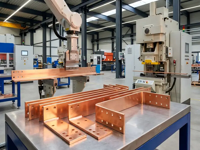
High-current power distribution systems—ranging from electric vehicle (EV) battery packs and energy storage systems (BESS) to industrial switchgear and power electronics—depend heavily on precision-fabricated copper busbars. Among electrical copper alloys, C11000 ETP (Electrolytic Tough Pitch) Copper remains the gold standard due to its unmatched electrical conductivity, thermal performance, and cold formability.
Manufacturing custom copper busbars CNC bending requires an integrated production approach. Because pure copper is a soft, ductile non-ferrous metal with a high work-hardening rate, improper tooling, punch clearances, or bend radii lead to burrs, micro-cracking, severe springback, or warped hole patterns.
This guide examines the engineering physics, CNC punching clearances, press brake bending formulas, electrotinning standards, and DFM rules required to produce high-precision C11000 copper busbars.
Table of Contents
C11000 ETP Copper Metallurgy & Material Selection for Busbars
Choosing the right grade and temper of copper is the first step in busbar engineering. C11000 ETP Copper contains a minimum copper purity of 99.90% (including silver) with a controlled oxygen content of approximately 0.02% to 0.04%.
Electrical and Thermal Properties
Per the ASTM B187 / B187M specification, C11000 offers an electrical conductivity of 100% IACS (International Annealed Copper Standard), equivalent to an electrical conductivity of 58.0 MS/m (megasiemens per meter) at 20°C. Its high thermal conductivity of 391 W/(m·K) enables busbars to rapidly transfer heat away from high-current junction points, preventing localized hot spots in sealed power enclosures.
| Property | Value (C11000 ETP Copper) | Engineering Impact |
|---|---|---|
| Copper Purity | ≥ 99.90% Cu (incl. Ag) | Maximizes current-carrying capacity |
| Electrical Conductivity | 100% IACS (58.0 MS/m) | Minimizes I²R resistive power losses |
| Thermal Conductivity | 391 W/(m·K) | Enhances heat dissipation in tight cabinets |
| Tensile Strength | 220–380 MPa (Temper dependent) | Determines structural rigidity under magnetic forces |
| Yield Strength (0.2%) | 69–310 MPa | Governs springback behavior during CNC bending |
| Density | 8.89 g/cm³ | Used for precise busbar weight and bus-duct calculations |
Temper Selection: Soft (O60) vs. Half-Hard (H02)
Busbar fabricators work primarily with two temper states for flat copper bar stock:
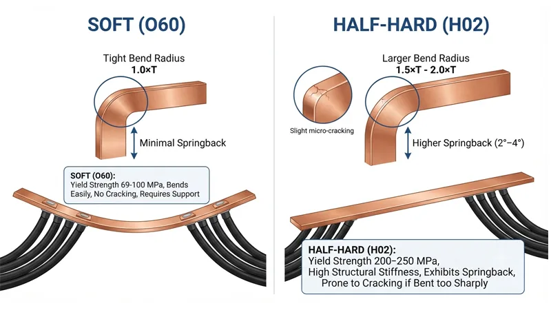
- Soft / Annealed (O60 Temper): Yield strength is approximately 69–100 MPa. Soft copper bends easily with minimal springback and zero micro-cracking risk, even at tight 1.0×T bend radii. However, soft bars bend under heavy cable load weights and require additional support standoffs.
- Half-Hard (H02 Temper): Yield strength ranges from 200–250 MPa. Half-hard copper provides structural stiffness for self-supporting switchgear bus assemblies. However, it exhibits higher springback (2°–4°) and requires larger inside bend radii (1.5×T–2.0×T) to prevent outer-surface fracturing.
Grain Direction Sensitivity
During cold rolling at the mill, copper grains elongate parallel to the rolling direction. When performing CNC bending:
- Transverse Bends (Perpendicular to Grain): The bend line crosses the elongated grains. This orientation resists cracking and allows tighter bend radii.
- Longitudinal Bends (Parallel to Grain): The bend line runs parallel to grain lines. The outer bend radius is prone to orange-peel texturing or surface micro-fissures. When longitudinal bends are unavoidable, the minimum inside radius must be increased by 20% to 50%.
CNC Busbar Punching Mechanics & Tooling Precision
Creating bolt holes, mounting slots, and voltage sensing cutouts in copper bar stock requires specialized CNC punching dies or multi-station hydraulic busbar processing centers. Unlike steel or aluminum, pure copper is prone to galling and heavy burr formation if punching parameters are misaligned.
Punch-to-Die Clearance Calibration
Punch clearance—the total distance between the punch diameter and the die opening diameter—must be calculated based on sheet thickness (T) and material shear strength.
For C11000 copper, optimal total clearance is 8% to 12% of material thickness per side:
- 3.0 mm Busbar: Punch clearance = 0.24 mm to 0.36 mm per side.
- 6.0 mm Busbar: Punch clearance = 0.48 mm to 0.72 mm per side.
- 10.0 mm Busbar: Punch clearance = 0.80 mm to 1.20 mm per side.
If punch clearance is too tight (< 5%), secondary shear occurs, causing high punch force, rapid tool wear, and galling. If punch clearance is too wide (> 15%), the copper is dragged into the die opening, creating a rounded rollover edge and large rollover burrs.
Punching Sequence:
Initial Tool Engagement → Plastic Deformation → Shear Crack Initiation → Clean Fracture & Slug Ejection
Hole Spacing and Edge Distance Guidelines
To prevent hole deformation, wall bulging, or material tearing during punching:
- Hole-to-Bar-Edge Distance: The distance from the edge of a hole to the bar boundary must be at least 1.5× material thickness (d ≥ 1.5T).
- Hole-to-Hole Distance: The web distance between two adjacent punch holes must be at least 2.0× material thickness (d ≥ 2.0T).
- Minimum Hole Diameter: Punching holes smaller than the bar thickness ($D < 1.0T$) causes excessive punch stem deflection and breakage. Holes smaller than $1.0T$ should be produced via CNC milling or drilling.
Burr Control and Deburring
In high-voltage busbar assemblies, burrs create concentrated electric field points that trigger electrical partial discharge or dielectric breakdown through insulation tubing.
An automated CNC punching process limits max burr height to under 0.05 mm (0.002 in). Following punching, parts undergo vibratory deburring or automated brush edge-rounding to create smooth 0.2–0.5 mm corner radii across all edges.
When requiring specialized hole shapes, threaded inserts, or complex step-milled profiles on thick copper stock, working with an experienced custom sheet metal fabrication services provider ensures tight tolerance control across low and high volume runs.
Copper Busbars CNC Bending: Formulas, Springback, and Tooling
Bending copper busbars involves plastic deformation where the outer fibers experience tension while inner fibers experience compression. Accurate CNC press brake bending relies on precise springback compensation, correct K-factor selection, and dedicated non-marking tooling.
Minimum Inside Bend Radius
To prevent outer-surface tensile tearing, the inside bend radius (R) must match material thickness and temper:
- Soft Temper (O60): Minimum inside radius R min = 1.0 × T.
- Half-Hard Temper (H02): Minimum inside radius R min = 1.5 × T (transverse) to 2.0 × T (longitudinal).
Springback Physics and Overbend Compensation
When the press brake ram retracts, the elastic energy stored in the copper bar relaxes, causing the bend angle to open slightly. This recovery is called springback (Δα).
Springback angle increases with higher material yield strength (sigma_y), larger bend radius (R), and smaller bar thickness (T). For C11000-H02 copper, typical springback ranges from 1° to 3° for a 90° bend.
To achieve an exact 90.0° finished angle, CNC press brakes utilize automated overbending and bottoming dwell cycles:
- CNC Overbending: The punch presses the copper bar past 90° (e.g., to 91.8°) so that elastic recovery returns the part precisely to 90.0°.
- Dwell at Bottom Dead Center: Holding hydraulic pressure at the bottom of the stroke for 0.5 to 1.0 seconds forces copper grains to re-align, significantly reducing springback variation across raw material batches.
Engineering calculations for overbend angles can be cross-referenced with established copper busbar bending springback calculations to calibrate press brake control parameters.
Bend Allowance (BA) and K-Factor Calculations
Accurate flat blank development prevents overall busbar length errors after multiple bends. Flat length calculation requires the Bend Allowance (BA) formula:
BA = π/180 × A × (R + K × T)
Where:
- A = Bend angle in degrees (e.g., 90°).
- R = Inside bend radius (mm).
- T = Material thickness (mm).
- K = K-factor (ratio of neutral axis location to thickness).
For C11000 copper air bending on a press brake:
- Soft Copper (O60): K ≈ 0.35
- Half-Hard Copper (H02): K ≈ 0.38 to 0.40
For detailed K-factor reference tables across varying V-die widths, consult K-factor and bend allowance guidelines for C110 copper.
Surface Plating & Insulation: ASTM B545 Tin Plating and Beyond
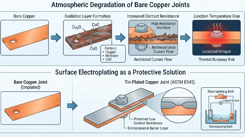
Bare copper exposed to atmosphere reacts with oxygen, moisture, and carbon dioxide to form copper oxide (Cu₂O and CuO) and copper carbonate films. These oxide layers are electrically resistive and lead to elevated contact resistance, localized heating, and thermal runaway at bolted busbar joints.
Atmospheric Exposure Flow:
Bare Copper → Oxidation Layer Formation → Increased Contact Resistance → Junction Temperature Rise
To preserve surface conductivity and prevent environmental degradation, surface electroplating is applied.
ASTM B545 Electroplated Tin Coatings
Tin plating is the most common, cost-effective surface treatment for copper busbars. Per ASTM B545 electroplated tin coating standards, electrodeposited tin coatings are categorized into service classes based on thickness:
| ASTM B545 Class | Minimum Thickness | Recommended Service Environment |
|---|---|---|
| Class A | 2.5 µm (0.0001 in) | Mild, indoor cleanroom or dry cabinet storage |
| Class B | 5.0 µm (0.0002 in) | Standard indoor switchgear and industrial enclosures |
| Class C | 8.0 µm (0.00032 in) | Severe indoor or protected outdoor power equipment |
| Class D | 15.0 µm (0.0006 in) | Highly corrosive, marine, or chemical plant environments |
Tin Whisker Mitigation & Nickel Underlayer
In high-density electronics and high-temperature environments, pure tin plating can form microscopic, needle-like single crystals known as tin whiskers. These electrically conductive whiskers cause short circuits between adjacent phases.
To prevent tin whisker growth and intermetallic diffusion, a nickel underplate (1.3 µm to 2.5 µm) is electrodeposited on the copper bar prior to tin plating. The nickel layer acts as a diffusion barrier, maintaining joint reliability over extended operating lifespans.
Alternative Surface Treatments
- Silver Plating (ASTM B700): Silver provides the lowest electrical contact resistance of any metallic coating. It is specified for high-voltage medium/heavy power switchgear joints and sliding disconnect contacts where operating temperatures exceed 100°C.
- Nickel Plating (ASTM B689): Offers superior wear resistance and corrosion protection in harsh marine or battery acid exposure environments.
- Dielectric Insulation (Heat-Shrink & Epoxy): For compact EV battery packs or busway enclosures, busbars receive heat-shrink PVC/polyolefin tubing or fluidized-bed epoxy powder coating, providing dielectric isolation up to 1000V AC / 1500V DC.
DFM Checklist & Common Custom Busbar Design Pitfalls
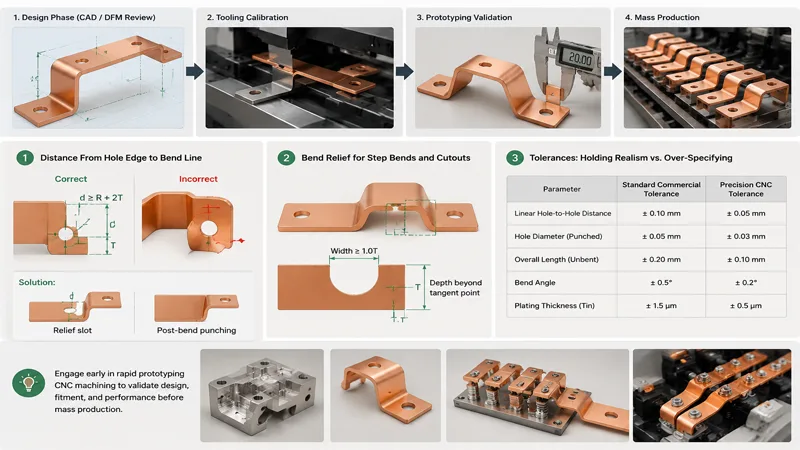
Integrating Design for Manufacturability (DFM) principles early in the CAD modeling stage reduces scrap rates, eliminates secondary machining operations, and lowers overall component cost.
Design Phase (CAD / DFM Review) → Tooling Calibration → Prototyping Validation → Mass Production
1. Distance From Hole Edge to Bend Line
When a punched hole is located too close to a bend line, the tensile stresses during bending drag the metal surrounding the hole, transforming a round hole into an oval slot.
- Rule: Minimum distance (d) from the edge of a hole to the start of the inside bend radius must be: d ≥ R + 2T
- Solution: If spatial constraints require a hole closer than $R + 2T$, punch a relief slot parallel to the bend line, or punch the hole after the bending operation using a secondary fixture.
2. Bend Relief for Step Bends and Cutouts
When bending a tab or section of a wide copper bar, the tearing force at the transition edge distorts the adjoining flat bar stock.
- Rule: Incorporate rectangular or radius bend relief cutouts at edge transitions. Relief width should be at least $1.0T$, and depth must extend past the tangent point of the bend radius.
3. Tolerances: Holding Realism vs. Over-Specifying
Setting unnecessarily tight tolerances drives up manufacturing costs without providing functional benefits.
| Parameter | Standard Commercial Tolerance | Precision CNC Tolerance |
|---|---|---|
| Linear Hole-to-Hole Distance | ± 0.10 mm | ± 0.05 mm |
| Hole Diameter (Punched) | ± 0.05 mm | ± 0.03 mm |
| Overall Length (Unbent) | ± 0.20 mm | ± 0.10 mm |
| Bend Angle | ± 0.5° | ± 0.2° |
| Plating Thickness (Tin) | ± 1.5 µm | ± 0.5 µm |
When developing custom power components or validating prototype geometries before mass production, engaging early in rapid prototyping CNC machining allows design teams to verify bend allowances, fitment, and thermal performance under real load conditions.
Evaluating a Custom Copper Busbar Manufacturing Partner
Selecting a qualified supplier for custom C11000 copper busbars requires evaluating technical capabilities, quality management systems, and transparent business practices.
Essential Capabilities Checklist
An ideal manufacturing partner should offer end-to-end processing under one roof:
- In-House CNC Fabrication: Hydraulic multi-station CNC busbar punching, shearing, and press brake bending centers.
- Precision Machining: 3-axis and 5-axis CNC turning and milling for thick step busbars, threaded standoffs, and liquid-cooled cold plates.
- Certified Plating Lines: Automated electrotinning, nickel, and silver plating lines compliant with ISO 9001 and IATF 16949 quality standards.
- Rigorous QA Inspection: Coordinate Measuring Machines (CMM), optical contour projectors, X-ray fluorescence (XRF) plating thickness gauges, and micro-ohm contact resistance meters.
- Material Traceability: Full Material Test Reports (MTRs) certifying 100% IACS conductivity and ASTM B187 chemical composition for every production lot.
As a full-service custom metal parts manufacturer, AFI Industrial Co., Ltd. (AFI Parts) brings over 20 years of experience serving automotive, energy storage, and industrial automation clients worldwide. By combining engineering review, transparent upfront pricing, and strict adherence to dimensional drawings, AFI Parts eliminates project delays and delivers certified, high-reliability busbar assemblies.
Frequently Asked Questions (FAQ)
C11000 ETP (Electrolytic Tough Pitch) Copper offers a minimum copper purity of 99.90% and delivers 100% IACS electrical conductivity (58.0 MS/m) along with high thermal conductivity (391 W/m·K). This minimizes I²R resistive power losses and ensures efficient heat dissipation in high-current power distribution systems like EV battery packs and industrial switchgear.
To prevent outer-surface tensile cracking during CNC bending, half-hard (H02) copper requires a larger inside bend radius—typically 1.5×T to 2.0×T (where T is sheet thickness)—compared to soft copper (1.0×T). Additionally, orienting bends transverse (perpendicular) to the rolling grain direction significantly reduces surface cracking risks.
The optimal punch-to-die clearance for C11000 copper punching is 8% to 12% of material thickness per side. Maintaining this clearance prevents secondary shear, excessive tool wear, galling, and burr formation, keeping maximum burr height below 0.05 mm.
Bare copper oxidizes in air, forming resistive oxide layers that increase electrical contact resistance and cause overheating at joints. ASTM B545 electroplated tin coatings protect copper from oxidation and galvanic corrosion. Applying a nickel underlayer (1.3 µm to 2.5 µm) before tin plating mitigates tin whisker growth in dense electronic assemblies.
To prevent hole elongation or tearing during press brake bending, the distance (d) from the edge of a hole to the start of the inside bend radius should follow the DFM rule d ≥ R + 2T. If space restrictions require placing a hole closer, a relief slot should be added or the hole should be machined post-bending.
Get Engineering Support and a Quote for Custom Busbars
Whether you are designing a high-density EV battery busbar, custom switchgear connection bars, or laminated power distribution assemblies, early DFM collaboration ensures optimal performance and cost efficiency.
Submit your 3D CAD files (STEP, IGES) and 2D engineering drawings to receive a complete DFM drawing review and a transparent custom metal fabrication quote from the engineering team at AFI Parts.