
Key takeaways
- Evaluate a peek‑dental‑abutments‑machining partner on verifiable standards, tolerances, and validation — not on capacity claims alone.
- Treat the implant connection geometry as a controlled precision feature, then back it with FAI, CMM, and surface-finish (Ra) evidence.
- Require ISO 13485 traceability, material CoA to ASTM F2026, and sterilization validation (ISO 11607, IQ/OQ/PQ) on the finished device.
- Use the RFQ checklist below to compare suppliers on documentation, ISO credentials, process capability, and DFM support before you qualify.
Successful PEEK dental abutments machining requires far more than just the ability to shape polymer; it demands a rigorous intersection of precision engineering, verifiable standards, and validated sterilization. When you shortlist a CNC partner for PEEK dental abutment machining or for PEEK-dental-abutments-machining as a defined service category, the real question is not whether a shop can cut PEEK. It is whether that shop can hold the tolerances, document the process, and hand over evidence you can defend in an audit.
That is why this guide is built around standards, tolerances, and validation rather than part counts. An OEM team needs a partner who can meet ISO compliance, control interface fit and surface finish, and deliver the documentation trail — first-article inspection, CMM reports, certificates of analysis — that makes regulatory and supplier review possible.
Work through this guide the way you would build an RFQ. Use each section to define what good looks like, so you can qualify suppliers on evidence, push back on vague answers, and reduce the risk that a dimensional or documentation gap surfaces late in a program.
Table of Contents
Regulatory and Compliance
Regulatory expectations shape nearly every downstream decision, from material choice to how you measure and what records you keep. Confirm where the device sits before you lock a machining and documentation strategy.
FDA Classification and 510(k) Scope
Dental healing abutments fall under the Class II regulatory umbrella for dental implant components. In the U.S., clearing a healing abutment ordinarily follows a 510(k) premarket notification demonstrating substantial equivalence to a predicate, with an abbreviated 510(k) built around the elements in 21 CFR 807.87. For abutments specifically, the FDA has also introduced a Safety and Performance Based Pathway with performance criteria for endosseous dental implants and abutments, which some sponsors use instead of a direct predicate comparison.
For your machining partner, the practical implication is that the interface geometry and materials drive equivalence. The FDA special controls for root-form endosseous implants and abutments expect the device, its intended use, and its labeling to be described clearly. Before you commission parts, confirm who owns the 510(k) and what design-locked geometry your machining supplier must reproduce to a controlled drawing revision.
ISO 13485, ISO 14971, and ISO 10993 Expectations
Manufacturing under an ISO 13485 quality management system is the baseline expectation for a medical-grade machining partner: it gives you design control, document control, traceability, and complaint and corrective-action handling. On top of that, ISO 14971 risk management should govern how the process is specified, and ISO 10993 biological evaluation defines the material’s tissue-contact performance.
Dental-grade PEEK is typically positioned for permanent mucosal membrane contact, which means the biocompatibility panel commonly spans ISO 10993-5 (cytotoxicity), ISO 10993-10 (sensitization and irritation), and often systemic toxicity, genotoxicity, and implantation depending on contact type and duration. As material suppliers note, resin and stock shapes are frequently assessed under these panels during production. Because machining changes the surface and extracted-residue profile, you should confirm that testing and evidence reflect the processed material and finished shape, not only the raw resin.
Material Standards and Traceability (ASTM F2026)
The partner to machining control is material traceability. For medical and implant-type PEEK, ASTM F2026 is the reference specification against which raw stock should be qualified, giving you a documented basis for chemistry, properties, and lot control. This is exactly where the brand AFI Industrial Co., Ltd. brings validated practice: in validated PEEK workflows, AFI handles raw-material certificate verification and full traceability from resin or stock-shape lot to finished abutment, so the document handoff you receive pairs every part number with its material certificate and lot records.
Key Takeaway: Require the machining partner to tie every delivery back to an ASTM F2026-compliant material certificate with full lot traceability. Otherwise a biocompatibility claim is hard to support in an audit.
Machining Capabilities and Controls
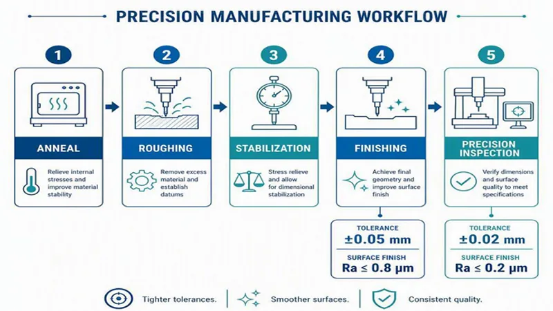
Precision PEEK dental abutment machining lives or dies on process control rather than machine horsepower. PEEK is a semi-crystalline thermoplastic that machines differently from metal: it does not shed heat the way steel does, and it relaxes after clamping is released. A capable partner controls heat, stress, and clamping rather than hoping the material stays put.
Tolerances, Thermal Management, and Stress Relief
Realistic PEEK machining tolerances start around ±0.05 mm on routine features and tighten to roughly ±0.02 mm when a process combines intermediate annealing with finish machining. Those tighter numbers are not automatic; they depend on a controlled sequence because PEEK moves as residual stress and heat relax.
The workflow that protects dimensional stability is staged: rough machine, stress-relieve or anneal, finish machine, apply a light spring pass to compensate for elastic recovery, then let the part thermally stabilize before any final measurement. Expect the machining partner to hold tolerance targets through that sequence and to share its approach to heat input, clamping pressure, and chip evacuation — the same precision CNC milling discipline AFI applies to tight-tolerance polymer work.
Tooling, Burr Control, and Surface Finish Targets
For a healing abutment, the tissue-contacting surface deserves as much attention as the dimensions. Sharp, positive-rake carbide (or PCD for longer runs and filled grades) shears the polymer cleanly, and climb milling with light cuts limits burrs and edge fuzzing. Compressed-air cooling lifts chips without thermal-shocking the part.
The roughness target is meaningful to the clinical outcome. Dental reviewers commonly recommend an Ra below 0.2 µm for soft-tissue sealing, and associate Ra below 0.8 µm with less bacterial colonization on abutment surfaces. Set the surface-finish requirement on the drawing and make sure the supplier measures it with a profilometer rather than treating smoothness as cosmetic. Burr-free edges and controlled secondary finishing should be part of the control plan, because aggressive deburring can round geometry you need to hold.
Clean Handling and Contamination Prevention
A machined polymer part that looks acceptable can still fail inspection if it carries chips, coolant residue, or machining debris. Clean handling matters for two reasons: contamination undermines surface-finish claims, and residual process chemicals can complicate a biocompatibility or extractables narrative. Confirm the partner’s housekeeping — dedicated or cleaned work zones, controlled cutting fluids, validated washing or cleaning steps, and lint-free packaging. This is where AFI’s documented biocompatible PEEK handling for contamination-sensitive applications supports the traceability story, so ask what clean-handling controls exist between machining, inspection, and packaging.
Interface Fit and Inspection
The distinguishing precision feature on a healing abutment is not the outer profile but the geometry that seats against the implant. This is where measurement strategy becomes a qualification question.
Implant–Abutment Geometry and Microgap Targets
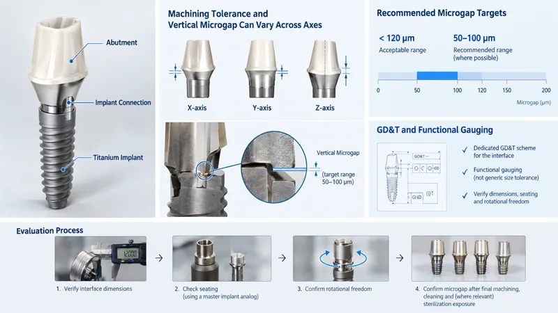
Analyze the implant connection as a controlled precision feature, not a cosmetic detail. Published work on PEEK and zirconia abutments over titanium implants shows machining tolerance and vertical microgap can vary meaningfully across axes, which is why the interface needs a dedicated GD&T scheme and functional gauging rather than a generic size tolerance. Clinical reviews treat a marginal gap under about 120 µm as acceptable and suggest adapting fit toward roughly 50–100 µm where possible.
What that means for evaluation is straightforward: verify the interface dimensions, seating, and rotational freedom, ideally against a master implant analog, and confirm the microgap on qualification builds after final machining, cleaning, and — where relevant — sterilization exposure.
Metrology Strategy: FAI, CMM, Vision, Profilometry
The right inspection method depends on the characteristic. First-article inspection (FAI) establishes the baseline on a qualification build. A coordinate measuring machine (CMM) captures the implant connection diameters, position, and profile in three dimensions. Vision systems add value on small, tight features and edge geometry, while a profilometer measures the Ra you placed on the surface-finish callout.
One detail matters more than most: measure after the part has thermally equilibrated. PEEK can move in the hours after machining, so FAI at room/controlled temperature, after any anneal and finish step, is the method that produces data you can defend. Ask which characteristics are measured by which instrument, and request the raw reports rather than a summary sentence.
Capability Metrics: Sampling Plans, Gage R&R, Cpk Goals
Inspection data only earns trust when the measurement system itself is trustworthy. For a regulated abutment line, request the partner’s measurement-system analysis — Gage R&R on the instruments that gate the critical interface features — and their process-capability targets, commonly a Cpk goal of 1.33 or higher on critical characteristics. Sampling plans should be defined, not improvised: first-article builds, lot acceptance, and any attribute or variable plans need documented logic. When AFI completes a precision PEEK run, the handoff AFI supplies typically includes the FAI/CMM reports and a certificate of analysis (CoA), so the capability data and the part-level evidence travel together.
Sterilization Compatibility and Validation
A healing abutment is shipped sterile, so the sterilization story is part of the design and process file. PEEK is generally compatible with all three common routes, but each must be validated on the finished, packaged device.
Steam, EtO, and Radiation Compatibility
PEEK tolerates steam autoclaving (typically validated around 134 °C under ISO 17665 principles), ethylene oxide (EtO, governed by ISO 11135 with aeration and residual testing), and gamma or electron-beam radiation (under ISO 11137 dosimetry). Manufacturer data shows PEEK retaining mechanical, dimensional, and structural performance across these routes — Solvay’s KetaSpire testing, for example, reports high resistance to gamma, steam, and EtO exposure.
Material compatibility is necessary but not sufficient. Each sterilization method has its own caveat to check: gamma can produce slight yellowing even when properties hold, and steam cycling can affect surfaces and fit over many repeats. Confirm which method your labeling requires, then let that drive package and validation choices.
Packaging (ISO 11607) and Sterilization Validation (IQ/OQ/PQ)
The sterile barrier system is validated against ISO 11607-1 (requirements and test methods for sterile-barrier and packaging materials) and ISO 11607-2 (validation of forming, sealing, and assembly). The equipment and process are then qualified through the standard IQ/OQ/PQ progression — installation, operational, and performance qualification — demonstrating that the package consistently maintains seal integrity and microbial barrier across runs.
As you validate, plan for cycle development, biological-indicator or dosimetry evidence as appropriate, and aged-package testing that reflects transport and shelf life. This is a multi-week effort, so it should appear early in the program, not as an afterthought at delivery.
Property Retention and Cosmetic Considerations Post-Sterilization
Sterilization validation ends with property-retention evidence on the finished device, not the raw resin. Span mechanical, dimensional, and cosmetic endpoints: retention or torque behavior, seating and fit, surface finish, and appearance. Because gamma can introduce a color shift, include an appearance specification if color matters for the product claim or customer acceptance.
Pro Tip: Ask whether the partner has a documented sterilization-compatibility position and can align package and cycle development with your sterilization provider. A partner who treats validation as a shared, early step reduces your risk of a late-cycle surprise.
RFQ Package and Supplier Qualification
A clear RFQ is the fastest way to separate capable polymer shops from generalist machinists. Specify the evidence you expect up front, and evaluate each supplier against the same checklist. Probe each area here when you qualify a precision CNC machining partner’s quality system, because documentation discipline predicts how well they will support a regulated program.
Drawings, GD&T, and Inspection Deliverables Checklist
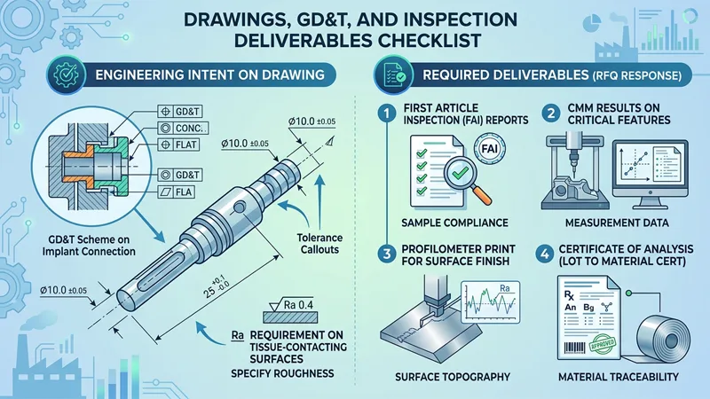
Put the engineering intent on the drawing: the GD&T scheme on the implant connection, the tolerance callouts, and the Ra requirement on tissue-contacting surfaces. Name the inspection deliverables you want in the RFQ response — FAI reports, CMM results on critical features, a profilometer print for surface finish, and a certificate of analysis tying the lot back to the material certificate.
ISO Credentials, Polymer Machining Evidence, and Scaling Capacity
Verify credentials with scope and registrar, not certificates alone. Ask about ISO 13485 coverage, and look for real polymer-machining evidence: past PEEK programs, controlled annealing workflows, and inspection data from earlier builds. Then test scaling capacity — can the partner move from prototypes to the volumes your program needs without losing the control plan? Consistency under a volume ramp is where many otherwise-strong shops stumble.
Lead Times, Communication, and DFM Support Alignment
Machining a precision polymer part benefits from an early design-for-manufacturability (DFM) conversation, because small drawing choices materially affect tolerances, tooling, and cost. Confirm lead times for first articles and production, and how engineering changes flow through document control. A partner like AFI Industrial Co., Ltd., whose process includes drawing review and DFM support alongside document handoff (FAI/CMM and CoA), aligns with the way OEM and engineering teams need to work — transparent, evidence-driven, and responsive across time zones.
Conclusion
Selecting a PEEK dental healing abutment precision machining partner — the kind of OEM‑grade peek‑dental‑abutments‑machining capability that healing‑abutment programs depend on — comes down to whether they can hold precise tolerances, demonstrate regulatory awareness, and hand you inspection and material evidence you can defend. Lead with the implant-connection GD&T and Ra targets, require ISO 13485 traceability to ASTM F2026, and treat sterilization validation as part of the program.
Build your RFQ around inspection deliverables and sampling/Cpk goals, validate package and sterilization cycles early, and schedule a supplier audit rather than accepting a capabilities slide deck. When a partner’s validated PEEK workflows and document handoff line up with your qualification criteria, you have a defensible foundation for a long-running, compliant program.
If you are qualifying a partner for precision PEEK dental components, AFI Industrial Co., Ltd. evaluates tolerant-to-clean workflows and supplies FAI/CMM reports and CoA with each delivery. Share your drawing to start the DFM and RFQ conversation.
FAQ
What tolerance can PEEK be CNC machined to?
What tolerance can PEEK be CNC machined to?
For a precision polymer part, the honest answer is “it depends on the process sequence.” On routine features, PEEK parts typically land in the ±0.05 mm range; the practical floor drops to roughly ±0.02 mm when the workflow adds an intermediate anneal or stress-relief step between roughing and finish machining. That tighter number is not free — PEEK relaxes as residual stress and heat dissipate, so a shop only holds it by thermally stabilizing the part and applying a light spring pass before final measurement. When you receive a drawing, put the tolerance callout in writing and ask the partner to confirm their sequence for achieving it, rather than accepting an untested best-case figure.
What surface finish (Ra) should I specify on a healing abutment?
What surface finish (Ra) should I specify on a healing abutment?
The target depends on what the surface must do. For the soft-tissue-sealing zone, reviewers commonly recommend an Ra below 0.2 µm, and surfaces under Ra 0.8 µm are associated with less bacterial colonization. Put the value on the drawing as a measurable callout, then make sure the supplier verifies it with a profilometer rather than treating smoothness as cosmetic. Because aggressive deburring can round the very geometry you need to hold on an interface feature, burr-free edges and controlled secondary finishing belong in the control plan alongside the roughness target.
Can PEEK dental healing abutments survive sterilization?
Can PEEK dental healing abutments survive sterilization?
Yes, PEEK is compatible with all three common routes: steam autoclaving under ISO 17665 principles, ethylene oxide (EtO) per ISO 11135, and gamma or electron-beam radiation per ISO 11137. Compatibility, though, is not the same as validation. Each method carries its own caveat — gamma can cause slight yellowing even when mechanical properties hold, and repeated steam cycles can affect surfaces and fit. The process must be validated on the finished, packaged device through ISO 11607 sterile-barrier requirements and the IQ/OQ/PQ sequence, not assumed from the raw material. Ask your partner to pair the material’s compatibility data with a documented package-and-cycle validation plan up front.
What quality and material standards should a PEEK abutment machining partner meet?
Look for three overlapping layers. On management systems, an ISO 13485 QMS covers design and document control, traceability, and corrective action, supported by ISO 14971 risk management and an ISO 10993 biological evaluation panel for tissue contact. On the material itself, raw stock should be qualified against ASTM F2026 so chemistry, properties, and lot control are documented. On delivery, the partner should hand over inspection evidence — FAI and CMM reports, a profilometer print, and a certificate of analysis that ties the lot back to the material certificate. A supplier who can produce all three layers together is far easier to defend in a regulatory audit than one offering only machining capacity.