
Key Takeaways:
- Precision harmonic drive flexsplines require tooth profile accuracy within ±3 µm to ±5 µm (ISO 1328 Class 4) and total radial runout under 3 µm to 5 µm.
- Thin-wall cup structures (0.5 mm to 1.5 mm thickness) demand hydraulic expansion mandrels and shallow hobbing pass depths (< 0.1 mm) to prevent elastic clamping distortion and tooth pitch errors.
- Quality verification requires continuous Statistical Process Control (SPC) with Cpk ≥ 1.33, full First Article Inspection (FAI) reports, and CMM gear metrology.
Introduction
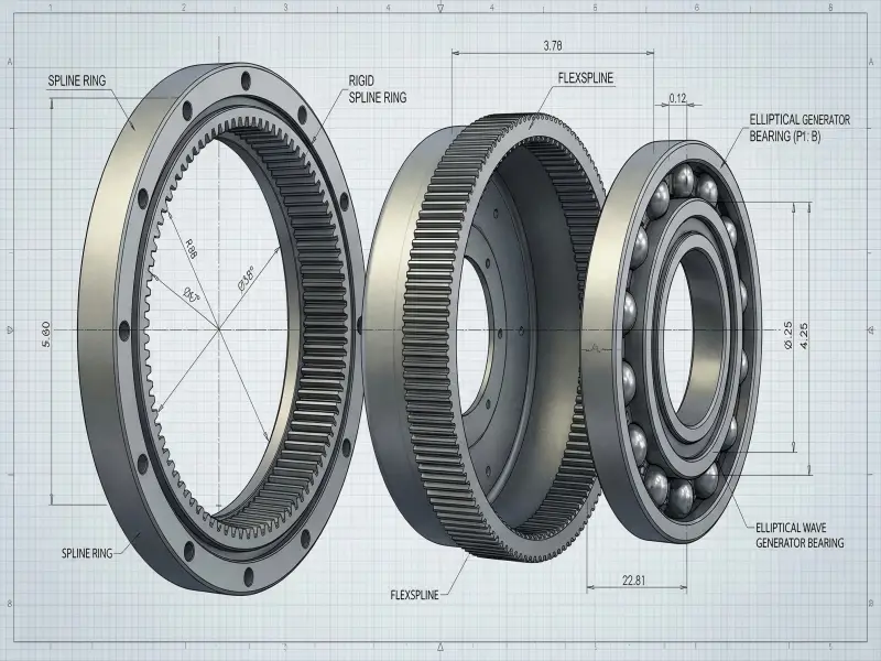
Harmonic drive speed reducers—also known as strain wave gears—are foundational components in precision robotics, semiconductor handling, aerospace gimbals, and automated industrial drives. At the heart of every strain wave gear set lies the flexspline: a thin-walled, flexible cylindrical cup with external gear teeth cut onto its open rim. Because the flexspline continuously deforms during operation under the action of an elliptical wave generator, manufacturing this component presents extreme machining and metallurgical challenges.
This technical guide focuses on end-to-end manufacturing workflows for custom flexsplines, exploring how partnering with a specialized flexspline hobbing CNC machining service can overcome these inherent challenges. Standard gear-cutting methods often fail on flexsplines due to thin-wall chatter, clamping deformation, and residual thermal stress. Achieving zero-backlash motion requires tight coordination between preform machining, specialized fixturing, hobbing parameters, and metrology.
This document serves mechanical design engineers, supplier quality engineers (SQE), and technical procurement managers evaluating custom gear manufacturing suppliers. Readers will gain actionable engineering insight into GD&T tolerance targets, thin-wall workholding mechanics, hobbing feeds and speeds, CMM inspection protocols, SPC capability release metrics (Cp/Cpk), production lead times, and supplier risk controls.
Design & Tolerances
Geometry and accuracy targets
A flexspline combines thin-wall cylindrical shell mechanics with high-density external gear teeth. The external teeth feature small gear modules (typically module 0.1 to 0.5 mm) with either modified involute or trochoidal tooth profiles designed to mesh smoothly with the rigid circular spline.
Holding tooth geometry accuracy is paramount for zero-backlash performance and uniform torque transmission. Target gear tooth quality must meet ISO 1328 Class 4 or DIN 3962 Grade 4 standards. Key dimensional targets include:
- Tooth Profile Error (f f): Maintained within ±3 µm to ±5 µm to avoid localized tooth interference.
- Single Pitch Deviation (fₚ): Held below 3 µm across adjacent teeth to ensure uniform load distribution across the engaged tooth zone.
- Total Pitch Cumulative Error (Fₚ): Controlled within 10 µm to 12 µm around the full 360° circumference.
Gear Quality Standard | ISO 1328 Class 4 / DIN Grade 4
Parameter | Target Specification Tooth Profile Deviation (ff) | ±3 µm to ±5 µm Adjacent Pitch Error (fp) | ≤ 3 µm Total Radial Runout (Fr) | ≤ 3 µm to 5 µm Wall Thickness Variation | ±0.005 mm
Table of Contents
Runout and concentricity controls
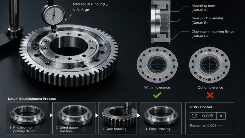
Concentricity and runout errors between the internal mounting bore, external gear pitch diameter, and diaphragm mounting flange directly cause angular transmission error and premature fatigue failure. Total radial runout (Fᵣ) of the gear pitch circle relative to the primary datum axis must not exceed 3-5 µm.
Establishing strict Geometric Dimensioning and Tolerancing (GD&T) datum structures is mandatory during soft turning and final finishing. Primary datum surfaces must be ground or precision-turned in a single setup before gear hobbing to eliminate cumulative chucking errors.
Thin-wall stability constraints
The wall thickness of a cup-type flexspline typically ranges between 0.5 mm and 1.5 mm, corresponding to roughly 1.5% to 3.0% of the outer cup diameter. This extreme slenderness ratio makes it highly susceptible to elastic deformation during mechanical clamping and cutting-force application.
To preserve wall stability:
- Material selection favors high-purity vacuum-degassed alloy steel (such as 40CrMo or 4340) or precipitation-hardened stainless steel (17-4PH) to maintain fatigue strength under cyclic elastic deformation.
- Stress-relief heat treatment cycles must be performed after rough turning to neutralize residual mechanical stresses before gear tooth hobbing.
- Case depth during surface hardening (such as gas nitriding) must be tightly controlled to 10–15% of total wall thickness (typically 50 µm to 80 µm) to prevent core embrittlement while providing wear resistance.
Process Flow
Cup forming and datum preparation
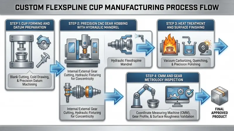
Manufacturing a precision flexspline begins with forging or bar stock preform processing, followed by CNC rough turning to establish basic cup geometry. The closed bottom diaphragm, mounting flange, and thin-wall cylindrical tube are machined with controlled wall allowance for subsequent grinding.
Datum preparation is critical before tooth cutting. The internal bore and axial reference face are finished to precise ground tolerances (H6/h6 limits). These surfaces act as the primary datum simulator during subsequent workholding, ensuring that reference axes remain stable across all processing stations. For detailed engineering criteria on reference surface alignment, review standard datum preparation and reference surface controls.
Flexspline Hobbing CNC Machining Service: Equipment and Cutting Parameters
Gear tooth generation relies on specialized high-precision CNC gear hobbing machines equipped with direct-drive torque motor spindles. Traditional mechanical chucking cannot be applied directly to thin-wall flexspline cups, as point-clamping forces cause ovality and irreversible wall deformation.
Instead, custom workholding employs hydraulically expanding mandrels or uniform diaphragm collets. These mandrels exert radial hydraulic pressure distributed evenly around the complete 360° internal bore of the cup wall, limiting radial clamping distortion to under 1.5 µm.
Flexspline Blank (Rough Turned)
Hydraulic Expanding Mandrel Clamping (Uniform Radial Pressure) CNC Hobbing Roughing Pass (Shallow Depth of Cut < 0.15 mm) CNC Hobbing Finishing Pass (Micro-Cutting Depth < 0.05 mm, High Speed) Stress Relief & Nitriding (Controlled Case Depth 50–80 µm) Electrolyte Deburring & Micro-Shot Peening
The hobbing process uses ultra-fine grain carbide hobs with physical vapor deposition (PVD) coatings (such as AlTiN or nACo). Hobbing parameters follow a micro-cutting strategy designed to limit cutting forces:
- Cutting Depth (aₚ): Roughing passes maintain radial engagement below 0.15 mm; finishing passes use micro-engagement under 0.05 mm per pass.
- Spindle Speed (n): Maintained between 1,800 RPM and 3,500 RPM to optimize chip formation and heat dissipation.
- Axial Feed Rate (f z): Set conservatively to 0.02 mm/rev to 0.05 mm/rev to minimize tooth flank scallops and tool mark height.
- Coolant Application: High-pressure oil jet cooling directed precisely at the tool-workpiece interface to wash away micro-chips and maintain thermal equilibrium.
For a comprehensive overview of multi-axis gear hobbing configurations, explore the CNC gear hobbing manufacturing process capabilities.
Finishing, deburring, and surface integrity
Following CNC hobbing, flexspline teeth must undergo deburring to remove micro-burrs at the tooth edges without altering tooth geometry. Manual filing or abrasive grinding is strictly forbidden. Suppliers use electrochemical machining (ECM) or micro-particle shot peening to achieve clean tooth flanks.
Micro-shot peening with fine ceramic beads generates beneficial compressive residual stresses on the tooth flanks and root fillets, significantly raising the fatigue endurance limit under cyclic elastic flexing. Final surface roughness (Rₐ) on tooth flanks and outer cylindrical surfaces is held below 0.4 µm (R z ≤ 1.6 µm).
Inspection & Metrology
Gear measurement and tooth errors
Quality verification of flexspline teeth requires automated CNC gear measuring centers equipped with 3D scanning probes. Gear analyzers scan the complete tooth profile along the tooth lead, evaluating involute curvature, lead crown, and pitch spacing.
Primary gear errors evaluated include:
- Profile Total Deviation (F_α): Checks conformity to the theoretical modified involute curve.
- Helix / Lead Deviation (F_β): Verifies parallelism along the axial width of the tooth.
- Pitch Deviation (f pt): Confirms consistent spacing between adjacent teeth to prevent motion ripple.
Datum, runout, and roughness checks
Coordinate Measuring Machines (CMM) featuring low-force scanning probes (measurement uncertainty < 1.5 µm) inspect thin-wall cup roundness, cylindrical coaxiality, and flange perpendicularity.
Optical non-contact profilometers measure surface micro-roughness (Rₐ, R z, Rₜ) across the gear teeth flanks and diaphragm flexure surfaces. Because mechanical contact probes can flex the ultra-thin cup wall during measurement, non-contact optical sensor heads are preferred for final acceptance.
FAI, SPC, and capability metrics
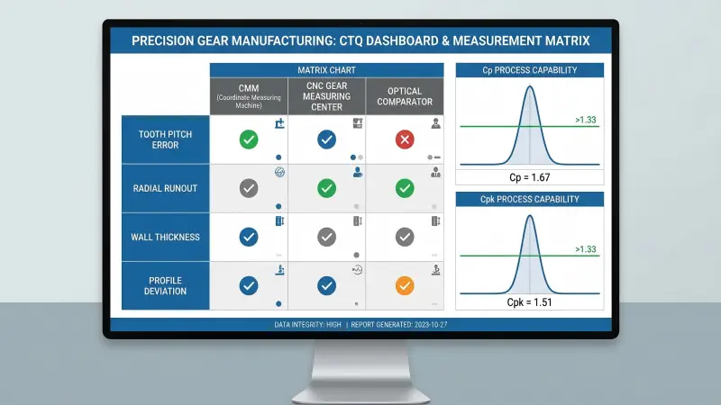
Supplier qualification relies on formal First Article Inspection (FAI) per AS9102 standards, verifying 100% of ballooned drawing dimensions across initial sample batches.
During serial production, Critical-to-Quality (CTQ) dimensions are tracked through Statistical Process Control (SPC) software. Process capability thresholds are defined as:
- Process Capability Index (Cₚ): Target ≥ 1.50.
- Process Capability Index (Cpk): Minimum acceptable threshold Cpk≥ 1.33 (with Cpk≥ 1.67 preferred for critical automotive or aerospace programs).
CTQ Feature | Inspection Instrument | Target Capability / Limit Tooth Profile & Pitch Error | CNC Gear Measuring Center | ISO 1328 Class 4 Wall Thickness Uniformity | Ultrasonic Thickness Gauge / CMM | ±0.005 mm (Cpk ≥ 1.33) Radial Runout & Concentricity | High-Precision CMM (Non-contact) | ≤ 0.005 mm (Cp ≥ 1.50) Surface Roughness (Ra) | Optical Profilometer | Ra ≤ 0.4 µm
Procurement & Supplier Selection
Lead times, cost drivers, and scalability
Procuring custom harmonic drive flexsplines involves specialized tooling, custom expanding mandrels, and rigorous quality validation cycles. Primary procurement metrics include:
- Prototype Lead Times: 2 to 4 weeks for initial samples, including custom fixture fabrication and DFM review.
- Production Lead Times: 4 to 6 weeks for batch production runs once FAI is approved.
- Primary Cost Drivers: High-purity alloy materials, custom mandrel tooling setups, specialized carbide hobs, heat treatment cycle duration, and 100% gear metrology time.
When planning production contracts, engineering teams should evaluate supplier scalability from rapid prototyping to low-volume production ramps. Exploring established tight-tolerance CNC machining services provides transparent baseline pricing and lead time models.
Capability signals and risk mitigation
To reduce sourcing risks when outsourcing flexspline manufacturing, procurement teams must verify key technical indicators during supplier audits:
- In-House Thin-Wall Fixturing Expertise: Supplier must demonstrate experience in designing custom hydraulic expansion mandrels and diaphragm chucks.
- Dedicated Gear Metrology Equipment: Verification that CNC gear measuring centers and high-accuracy CMMs are installed in climate-controlled inspection rooms (20°C ± 0.5°C).
- Traceable Quality Documentation: Supplier must provide full 3.1 material test certificates, heat treatment hardness/case depth reports, FAI documentation, and live SPC control charts.
Risk Factor: Thin-Wall Clamping Distortion, Heat Treatment Ovality, Tooth Pitch Error Drift, Sourcing Lead Time Delays
Mitigation Protocol: Mandrel hydraulic load limits, vacuum stress-relief annealing, closed-loop SPC tool wear tracking, pre-qualified material stock
Partnering with AFI Industrial Co., Ltd.
For global OEMs and engineering firms seeking reliable manufacturing partners for custom precision components, AFI Industrial Co., Ltd. (AFI Parts) provides comprehensive custom machining and gear hobbing services.
AFI Industrial Co., Ltd. brings dedicated engineering capabilities to complex flexspline projects:
- Custom Thin-Wall Fixturing: Engineering teams design and produce bespoke hydraulic expanding mandrels and low-deformation workholding to preserve cup roundness during high-speed hobbing.
- Advanced Gear Metrology: In-house CNC gear measuring centers and high-precision CMMs inspect tooth profiles, pitch errors, and runout down to single-digit micron tolerances.
- Audit-Ready QA Framework: Full FAI (AS9102) documentation, material chemical/mechanical certifications, and continuous SPC tracking (Cpk≥ 1.33) ensure complete batch traceability and consistent quality release.
FAQ
What are the primary machining challenges in producing custom flexsplines?
The main challenges stem from the flexspline’s extremely thin wall structure (0.5 mm to 1.5 mm). Standard clamping and cutting forces easily cause elastic distortion, chatter, and ovality. Additionally, cutting high-density external teeth with profile tolerances held to ISO 1328 Class 4 (±3 µm to ±5 µm) requires specialized low-force hobbing techniques and strict residual stress control.
Why are hydraulic expanding mandrels required during CNC hobbing?
Traditional mechanical jaw chucks exert localized point-clamping forces that permanently deform thin-walled cups. Hydraulic expanding mandrels distribute uniform radial hydraulic pressure across the complete 360° internal bore, restricting radial clamping distortion to under 1.5 µm and preventing tooth pitch cumulative errors.
Which materials and heat treatments are optimal for flexspline manufacturing?
High-purity vacuum-degassed alloy steels (such as 40CrMo or 4340) and precipitation-hardened stainless steels (such as 17-4PH) are preferred for high fatigue endurance. Heat treatments must include stress-relief annealing after rough turning and controlled gas nitriding, maintaining case depth between 10% and 15% of total wall thickness (50 µm to 80 µm) to ensure wear resistance without core embrittlement.
How is tooth profile accuracy measured without deforming the thin-wall structure?
Metrology relies on automated CNC gear measuring centers equipped with low-force 3D scanning probes and non-contact optical profilometers. Non-contact sensors prevent physical contact probes from deflecting the flexible cup wall during surface roughness and tooth profile scans.
What process capability (Cpk) threshold is standard for custom flexspline quality release?
For Critical-to-Quality (CTQ) gear features, suppliers must maintain a minimum Process Capability Index (Cpk) ≥ 1.33 under continuous Statistical Process Control (SPC). For demanding robotics, aerospace, and medical applications, Cpk ≥ 1.67 is frequently required.
What are the typical prototype and production lead times for custom flexsplines?
Prototype lead times generally range from 2 to 4 weeks, including DFM engineering review, custom fixture fabrication, and sample production. Full batch production runs typically require 4 to 6 weeks following First Article Inspection (FAI / AS9102) approval.
Conclusion
Manufacturing custom harmonic drive flexsplines requires strict engineering discipline across every phase of production. Because thin-walled cups are inherently prone to distortion, success hinges on pairing precision preform turning with custom hydraulic expansion fixturing, low-force CNC hobbing strategies, and rigorous post-machining surface treatment.
Holding single-digit micron profile tolerances and radial runouts under 5 µm is impossible without an integrated metrology framework. Procurement and engineering teams must insist on verifiable CMM inspection data, gear analyzer charts, and Cpk process capability metrics before approving production tooling.
When initiating new custom flexspline projects, procurement teams should provide complete CAD models, GD&T drawings with specified datum reference frames, target module/tooth counts, and material grade requirements. Partnering with experienced manufacturing providers like AFI Industrial Co., Ltd. streamlines DFM review cycles, accelerates prototype release, and ensures long-term supply chain reliability.