
Introduction
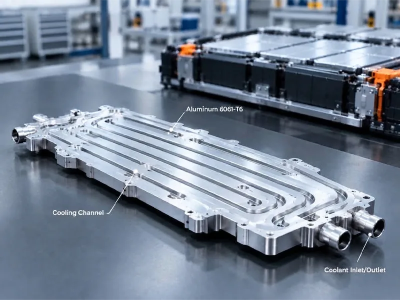
When you’re sourcing Aluminum 6061-T6 Liquid-Cooled Plates for EV battery packs, two realities collide: your thermal design evolves faster than your production ramp, and a single field leak can cost more than your entire prototype budget. CNC milling bridges this gap for prototype-to-mid-volume programs by letting you iterate channel geometry, sealing interfaces, and port configurations without tooling penalties—while still delivering the dimensional control and leak integrity PPAP and production require.
This is not a generic primer on cooling plates. This guide walks you through the critical-to-quality (CTQ) specifications, process controls, and PPAP deliverables that purchasing managers and supplier quality engineers must verify before signing a PO. You will learn how to specify channel tolerances that preserve your CFD-validated hydraulic performance, define flatness and sealing-land requirements that prevent costly leak escapes, and align test methods and acceptance limits with automotive quality systems. By the end, you will have an actionable framework to reduce defect rates, eliminate ambiguity in supplier communication, and protect your total cost of ownership.
Whether you are qualifying a new Tier 2 machining supplier or deciding between CNC milling and brazed alternatives for a 5,000-unit annual run, the specifications and controls in this guide will help you make informed sourcing decisions and avoid the most common failure modes in cooling plate production.
Table of Contents
DFM for Channels and Sealing
The thermal performance you validated in simulation depends entirely on manufacturing’s ability to reproduce your channel geometry and maintain leak-tight seals under pressure cycling. Small deviations in channel width or depth can shift pressure drop by 20% or more, while imperfect sealing lands guarantee field failures. Design for manufacturability starts with understanding what CNC milling can reliably hold and how to specify the features that matter.
Channel Geometry Targets
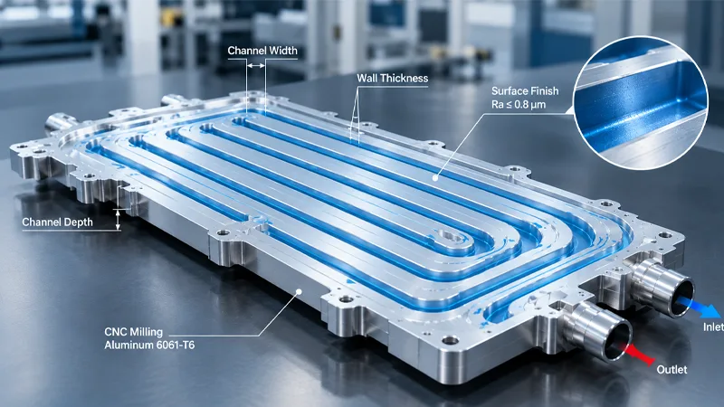
Channel design in a liquid cooling plate directly trades off heat transfer effectiveness against pumping power. Narrower, deeper channels increase surface area and turbulence, improving heat extraction but raising pressure drop. Wider, shallower channels reduce pump load but sacrifice thermal performance. Your CTQ specification must preserve the hydraulic diameter and flow distribution validated in your CFD model.
For CNC-milled 6061-T6 plates, practical channel widths range from 0.3 mm to 6 mm, with wall thickness between adjacent channels as thin as 0.15 mm to 0.2 mm for microchannel designs. Standard rectangular serpentine channels commonly measure 2 mm × 1.5 mm to 20 mm × 6 mm depending on heat flux and pressure budget. The key manufacturing control is positional tolerance: misalignment of even 0.5 mm in a multi-pass serpentine layout can create dead zones or short-circuit flow paths that degrade thermal uniformity.
Specify channel dimensions as ±0.05 mm for microchannels and ±0.1 mm for standard channels, with a note that all channels in a parallel-flow array must maintain uniform cross-sectional area within ±5% to prevent flow maldistribution. Include a requirement for post-machining dimensional inspection on at least three channels per plate using CMM or optical methods, with results documented in your PPAP package.
Surface finish inside coolant channels directly affects pressure drop and long-term fouling. The automotive standard for machined cooling passages is Ra ≤ 0.8 μm. Rougher surfaces increase friction factor and provide nucleation sites for scale buildup in glycol-water coolants. Specify the finish requirement and ask your supplier how they validate it—many shops claim microchannel capability but lack the portable roughness testers or process controls to verify sub-micron finishes in narrow, deep features.
Sealing Lands and Gasket Strategy
A leak in a battery cooling plate is not a warranty claim—it is a safety incident. Your sealing strategy must account for thermal expansion, assembly stack-up, and pressure transients over the full service life. For CNC-milled plates, this means designing continuous, flat sealing lands with controlled surface quality and sufficient width to accommodate gasket compression without extrusion.
The sealing land must be machined flat and parallel to the battery contact surface. Flatness tolerance on the sealing perimeter should match or exceed your cover-plate joint requirement, typically ≤0.05 mm across the sealing path. Surface finish on the sealing land should be Ra ≤ 3.2 μm to ensure conformable contact with elastomeric gaskets or Ra ≤ 1.6 μm for metal-to-metal compression seals. Any nicks, burrs, or machining chatter marks in the sealing zone are reject conditions.
Sealing land width depends on gasket type and bolt spacing. For formed-in-place gaskets or silicone beads, a 4–6 mm land width is common. For preformed elastomeric gaskets, the land must be sized to the gasket cross-section with enough margin to prevent extrusion under clamp load. If you are using a cover plate with through-bolts, ensure bolt holes are positioned to distribute clamping force evenly across the seal perimeter—unsupported spans longer than 80–100 mm between bolts can allow leakage under thermal cycling.
Your design review checklist should include: Is the sealing land continuous with no interrupted paths? Are all internal channels set back from the seal zone by at least 2× the channel depth to prevent breakthrough? Is the land surface free of cross-drilling intersections or undercut features that trap air or create leak paths?
O-Ring Grooves per ISO 3601
If your cooling plate design uses O-ring seals at inlet/outlet ports or cover-plate joints, groove dimensions must follow ISO 3601 standards to ensure proper squeeze and prevent seal extrusion. CNC milling offers precise control of groove depth, width, and corner radii, but only if you specify the requirements correctly.
For static face seals in a cooling plate operating at 3–5 bar, typical O-ring groove depth is 70–85% of the O-ring cross-section diameter, with groove width 10–30% wider than the O-ring diameter. A 3 mm O-ring, for example, would sit in a groove approximately 2.1–2.5 mm deep and 3.3–3.9 mm wide. The squeeze percentage should be 10–20% for elastomers like NBR or EPDM in automotive coolant service.
Corner radii in the groove are critical. Sharp internal corners concentrate stress and accelerate seal degradation. Specify a 0.2–0.4 mm radius at the bottom corners of the groove, achievable with standard end mills. Avoid specifying radii smaller than the tool nose radius unless you are willing to accept EDM or custom tooling upcharges.
Surface finish in the O-ring groove should be Ra ≤ 1.6 μm to minimize friction during assembly and prevent abrasion of the seal during pressure cycling. Document groove dimensions and finish requirements in your control plan and require first-article inspection with an optical comparator or pin gauge verification for groove width and depth.
Machining Controls and Fixturing
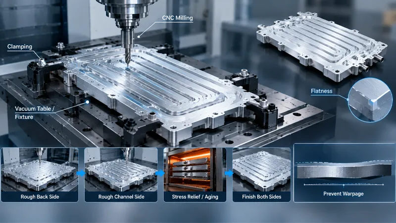
CNC milling removes material asymmetrically, and aluminum 6061-T6 is a relatively soft alloy that deflects under cutting forces. Without proper fixturing strategy and process sequencing, you will get plates that warp after final machining, fail flatness inspection, or arrive with burrs that contaminate coolant circuits. Machining controls are where you separate qualified suppliers from quote mills.
Warpage and Symmetric Material Removal
Residual stress in aluminum plate stock is a fact of life. When you machine deep pockets or remove significant material from one side, you release those stresses and the part bends. The key mitigation is symmetric material removal and stress-relief fixturing.
Your supplier should rough both sides of the plate in alternating passes before finish machining either face. For a cooling plate with channels on one side and a flat battery-contact surface on the other, the process sequence should be: rough machine the back side to near-final thickness, flip and rough machine the channel side to depth, stress-relieve or age the part if thickness variation exceeds 3 mm, then finish machine both sides in a single setup if possible.
Fixturing must support the part without inducing bending. Vacuum tables work well for thin plates under 5 mm, but thicker plates or parts with deep channels may require custom soft-jaw fixtures or magnetic chucks with multiple contact points. Clamp force should be distributed across the plate perimeter, not concentrated at corners. Over-clamping a thin-walled section during finish milling will deform the part, and it will spring back after unclamping, leaving you with out-of-flat geometry that no secondary operation can fix economically.
Ask your supplier: What is your fixturing strategy for this geometry? Do you rough both sides before finishing? What is your scrap rate for flatness on similar parts? A supplier who cannot answer these questions is guessing, and you will pay for their learning curve in scrap and rework.
Flatness and Surface Finish CTQs
Flatness of the battery-contact surface is the most critical dimensional specification for thermal performance. Even a 0.1 mm deviation can double thermal interface resistance if your TIM pad is thin or your clamping strategy is non-uniform. The automotive standard for high-performance EV cooling plates is flatness ≤0.05 mm across the contact area, though ≤0.2 mm is acceptable for less demanding applications with thicker thermal pads.
Flatness is measured after all machining and finishing operations, with the part free of clamping forces and thermally stabilized to ambient temperature. Use a CMM with multiple touch points across the surface, or a surface plate with feeler gauges if you are qualifying a lower-volume supplier. Do not accept flatness claims based on the machine’s calibration—measure the part.
Surface finish on the battery-contact face should be Ra ≤ 1.6 μm to ensure good TIM wetting and consistent thermal contact. Rougher surfaces trap air pockets and increase contact resistance. The finish is typically achieved by face milling with a sharp insert followed by a light finishing pass at high spindle speed. Avoid specifying mirror finishes unless your assembly process truly requires it—you will pay a premium for grinding or lapping operations that add little thermal value.
For the coolant-wetted channel surfaces, as noted earlier, Ra ≤ 0.8 μm is the target to minimize pressure drop and fouling. Verify finish with a portable profilometer on accessible channels, and require your supplier to demonstrate measurement capability during PPAP.
Burr Control, Deburring, and Cleaning Setup
Burrs are the silent killer of cooling plate quality. A single aluminum chip trapped in a channel can migrate during operation, block flow, or score a seal face during thermal cycling. Burr control starts with tool selection and cutting parameters, but it must be followed by a validated deburring and cleaning process.
CNC milling of soft aluminum generates burrs at every tool exit edge. Sharp tooling, climb milling, and optimized feeds minimize but do not eliminate them. Your supplier must have a documented deburring procedure—manual, vibratory, or abrasive flow machining—with defined acceptance criteria. For critical sealing edges and O-ring grooves, manual deburring with inspection under magnification is standard. For internal channels, vibratory tumbling with ceramic media or brush deburring may be acceptable if the process is validated not to embed media particles in the aluminum.
Cleaning after deburring is non-negotiable. Residual cutting fluid, aluminum fines, and media dust will contaminate your coolant and clog restrictive orifices. The standard cleaning protocol is alkaline wash, rinse, and dry in a closed-loop system with filtration. Some programs require ultrasonic cleaning for microchannel plates. After cleaning, the plate should be inspected under UV light for residual contamination and verified particle-free by flushing with filtered solvent and inspecting the catch screen.
Ask to see your supplier’s cleaning validation report. It should document particle counts before and after cleaning, residue chemistry analysis, and a defined acceptance limit. If they cannot show you this data, they are not cleaning to automotive standards.
Leak and Pressure Testing Methods
Every cooling plate must be leak tested before it enters your assembly line. The only questions are which method, what acceptance limit, and how to maintain traceability. The testing strategy must balance sensitivity, cycle time, and cost, and it must integrate into your PPAP and production control plans.
Helium Mass Spectrometry Testing
Helium mass spectrometry is the gold standard for leak detection in EV cooling plates because it can detect leaks down to 10⁻⁹ atm·cc/s, far below the threshold where coolant loss becomes measurable. For safety-critical battery thermal systems, this sensitivity is often required to ensure no moisture ingress path exists that could lead to short circuits or electrolyte contamination.
The typical test sequence for a cooling plate is: seal all ports except one inlet and one outlet, connect to a helium leak detector, evacuate the test chamber, pressurize the internal circuit with helium at 3–5 bar, and measure helium concentration in the vacuum chamber with a mass spectrometer. If the measured leak rate exceeds your acceptance limit, the part is rejected. Test cycle time is 60–90 seconds, including evacuation and stabilization.
For water-glycol EV cooling circuits, a common acceptance limit is ≤10⁻⁸ mbar·L/s. For refrigerant-based cooling or high-reliability programs, limits as tight as 10⁻⁹ atm·cc/s are specified. The specific limit should be derived from your coolant loss budget over the service life and the consequence of leakage—battery pack circuits with direct cell contact typically require tighter limits than module-level or pack-level coolant loops.
Helium testing is expensive and requires skilled operators and calibrated equipment. It is cost-effective for 100% testing in low-to-mid-volume production, but it may become a bottleneck above 10,000 units per year unless you invest in automated multi-station systems. Many suppliers offer helium testing as part of PPAP but switch to pressure decay for production unless you contractually require helium as the ongoing test method.
When specifying helium leak testing in your PO, include: test pressure, acceptance limit, dwell time, and traceability requirements. Require test results to be recorded per serial number and provided with each shipment.
Pressure-Decay and Proof/Burst Tests
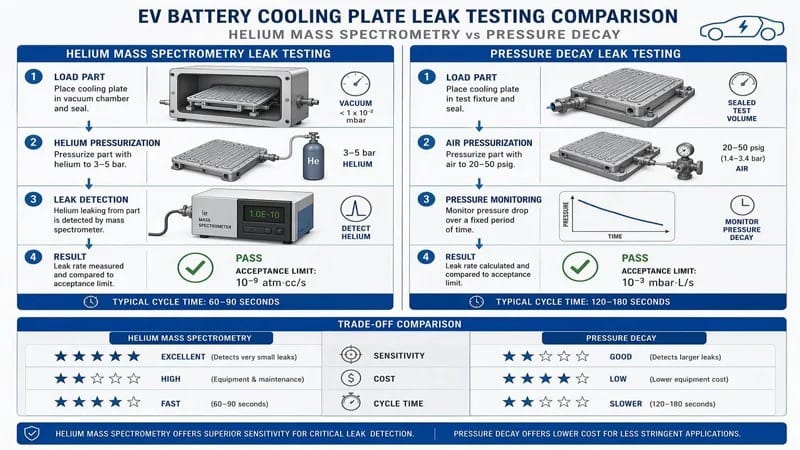
Pressure decay testing is the workhorse method for production screening. It is faster and cheaper than helium testing, though less sensitive. In a pressure decay test, the cooling plate is pressurized with air or nitrogen to a specified pressure—typically 20–50 psig depending on the circuit operating pressure—and the pressure is monitored over a timed interval, usually 60–180 seconds. A pressure drop exceeding the acceptance threshold indicates a leak.
The major limitation of pressure decay is sensitivity to temperature variation. A 1°C temperature change in the test gas can create a pressure change that mimics a small leak. To get reliable results, the test must be conducted in a temperature-controlled environment, or the system must compensate for temperature drift. Many automotive suppliers use differential pressure decay testers that reference a sealed master part to cancel out environmental effects.
Typical acceptance limits for pressure decay on EV cooling plates are ≤0.5 mbar/min or ≤1 psi drop over 120 seconds, but these are rule-of-thumb values. The right limit depends on the internal volume of your plate, the test pressure, and the temperature stability of your test environment. Work with your supplier to validate the correlation between pressure decay and actual leak rate, and document the test parameters in your control plan.
Proof testing and burst testing are separate requirements that verify structural integrity. A proof test pressurizes the plate to 1.5× the maximum operating pressure and holds for a specified time without leakage or permanent deformation. A burst test pressurizes to failure to confirm the safety margin. Burst pressure for a well-designed 6061-T6 cooling plate with 2 mm wall thickness between channels and the outer face is typically 15–25 bar, depending on channel depth and geometry. Proof and burst tests are usually performed on a sample basis during PPAP and at regular intervals during production, not on every part.
Acceptance Limits and Test Conditions
Setting the correct acceptance limit requires balancing leak detection sensitivity with practical test capability and cost. A limit that is too tight generates false rejects and inflates scrap cost. A limit that is too loose allows marginal parts into production that fail in the field.
For helium mass spectrometry, start with the leak rate that corresponds to your allowable coolant loss over the warranty period. If your system holds 2 liters of coolant and you can tolerate 10% loss over 10 years, that is roughly 20 mL per year or 0.6 mL per year per plate in a 30-plate pack. Convert this to a helium-equivalent leak rate using the molecular weight ratio—helium leaks approximately 3× faster than water vapor through the same orifice. This gives you a physics-based acceptance limit, not an arbitrary number copied from another program.
For pressure decay, the acceptance limit is often set empirically by testing known-good parts and known-leaky parts and defining a threshold that separates them with margin. Many suppliers use ≤1 psi drop over 120 seconds at 30 psig as a default for aluminum cooling plates, but you should validate this limit against your helium test results during PPAP to confirm correlation.
Test conditions must be documented and controlled. Specify the test pressure, dwell time, temperature range, port configuration, and any fixtures or adapters required. Require your supplier to include test equipment calibration records and gage R&R studies in the PPAP package to demonstrate measurement system capability. If you are using pressure decay, the MSA should show that temperature compensation or environmental control is adequate to achieve repeatability within 10% of your acceptance limit.
Surface Protection and Compatibility
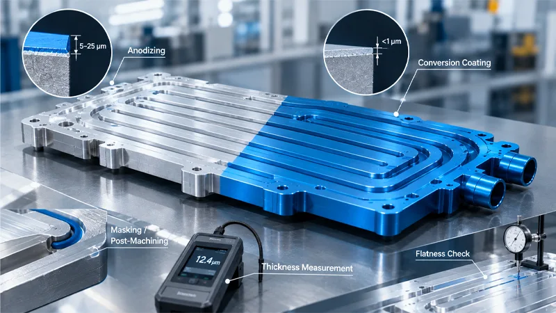
A cooling plate that passes dimensional and leak inspection can still fail in service if the surface protection strategy is incompatible with your coolant chemistry or assembly process. Aluminum 6061-T6 is highly corrosion-resistant in neutral-pH environments, but it will degrade rapidly if exposed to chlorides, acidic coolants, or galvanic coupling with dissimilar metals. Your surface treatment and material compatibility plan must address these risks.
Anodizing and Conversion Coatings
Type II anodizing is the most common surface protection for aluminum cooling plates in automotive service. The anodic layer is typically 5–25 μm thick, depending on specification, and provides excellent corrosion resistance and a hard, wear-resistant surface. Anodizing also improves surface emissivity, which can benefit thermal performance in air-cooled sections of the battery pack.
The challenge with anodizing is dimensional control. The anodic layer grows both into the base metal and above the original surface, so it adds thickness to all exposed faces. If your sealing land or O-ring groove dimensions are critical, you must either mask those surfaces during anodizing or machine them after anodizing. Masking adds cost and complexity. Post-anodize machining removes the protective layer in the machined area, so you need to evaluate whether that is acceptable for your application.
Conversion coatings—chromate or non-chromate chemical treatments—are a lower-cost alternative that adds minimal thickness, typically <1 μm. They provide moderate corrosion resistance and a good base for paint or adhesive bonding, but they do not offer the abrasion resistance of anodizing. Conversion coatings are common in cost-sensitive applications or where dimensional tolerance on sealing surfaces is tight.
Specify the coating type, thickness, and any masking requirements in your drawing and PO. Require your supplier to demonstrate coating thickness measurement capability—eddy current or micrometer methods—and include coating thickness results in the dimensional report. If you are using anodizing and your flatness tolerance is tight, consider requesting a flatness measurement both before and after coating to verify that the coating process does not induce warpage.
Coolant Chemistry and Galvanic Risks
Aluminum 6061-T6 is compatible with most automotive coolants, but compatibility is not automatic. The coolant must be aluminum-safe, meaning it contains corrosion inhibitors that protect aluminum from pitting and maintain pH in the neutral range (pH 7–9). Ethylene glycol and propylene glycol coolants are both acceptable if properly inhibited. Deionized water is safe in the short term but can cause corrosion if trace contaminants are present or if the system is not properly passivated.
The most common coolant-related failure mode is galvanic corrosion. If your cooling circuit includes copper, brass, or steel fittings in direct coolant contact with the aluminum plate, a galvanic cell forms and the aluminum corrodes preferentially. The risk is highest in mixed-metal systems with poor electrical isolation. Mitigation strategies include using all-aluminum components in the coolant path, electrically isolating dissimilar metals with plastic inserts or gaskets, or using a coolant with galvanic corrosion inhibitors.
Your supplier should provide material certification for the 6061-T6 alloy and confirm that no incompatible filler metals or joining consumables are used in plate fabrication. If brazing or welding is part of the process, verify that filler alloy composition is documented and compatible with your coolant. Include coolant chemistry compatibility as a line item in your DFMEA and ensure your control plan includes periodic inspection for corrosion during pilot builds.
Masking Critical Faces and Torque/Seal Effects
Anodizing or coating the sealing land can affect seal performance. A 15 μm anodic layer adds surface hardness, which reduces gasket embedment and can increase the clamping force required to achieve target squeeze. If your assembly uses elastomeric gaskets with a defined squeeze percentage, you may need to adjust gasket dimensions or bolt torque specs to account for the coated surface.
Masking the sealing land during anodizing eliminates this variable, but it adds cost and introduces the risk of incomplete masking or coating bleed. A practical compromise is to anodize the entire part and then lightly lap or grind the sealing land after coating to restore the original surface finish and remove any coating irregularities. This gives you corrosion protection on coolant-wetted surfaces while maintaining dimensional and seal-performance control on the joint.
Document your masking or post-coat machining strategy in the process flow diagram and control plan. If sealing surfaces are machined after coating, specify the final surface finish and flatness requirements and require re-inspection after the final operation.
PPAP/IATF 16949 Deliverables
Production Part Approval Process (PPAP) is your contractual assurance that the supplier can consistently produce parts that meet your specifications. For liquid cooling plates in an EV battery pack, PPAP is not a formality—it is the gate that determines whether your launch stays on schedule or slides into a crisis. Understanding what to require and how to review the package is a core competency for automotive purchasing and quality teams.
Control Plan, PFMEA, and MSA
The control plan is the operational backbone of your supplier’s quality system. It defines every inspection, test, and reaction plan across the full production process from incoming material receipt to final shipment. For a CNC-milled cooling plate, the control plan must address raw material certification, in-process dimensional checks during machining, post-machining cleaning validation, leak testing, surface finish verification, and packaging controls to prevent handling damage.
Special characteristics—dimensions or features that affect safety, regulatory compliance, or fit/function—must be clearly marked in the drawing and carried through into the control plan. For a cooling plate, typical special characteristics include channel dimensions, flatness, sealing land geometry, and leak test results. Each special characteristic must have a defined control method, sampling frequency, and reaction plan if the process drifts out of specification.
The Process FMEA (PFMEA) is the risk analysis that feeds the control plan. It identifies potential failure modes at each process step and defines preventive and detective controls to reduce risk. For CNC machining of cooling plates, high-risk failure modes include tool wear leading to dimensional drift, fixturing error causing warpage, inadequate cleaning leaving contamination, and leak test equipment malfunction allowing defects to escape. The PFMEA should show that these risks are addressed with controls like tool life monitoring, fixture validation, cleaning process audits, and leak tester calibration with traceable standards.
Measurement System Analysis (MSA) demonstrates that your inspection and test equipment can reliably distinguish good parts from bad parts. For a cooling plate, MSA studies are required for any gage used to measure special characteristics. At a minimum, this includes the CMM for dimensional inspection, the leak tester, and the surface finish profilometer. The MSA should show acceptable gage R&R—typically <10% of tolerance for critical features—and document operator training and certification.
Review the PFMEA and control plan together during supplier selection. They should reference the same process steps and special characteristics. If the PFMEA identifies a high-risk failure mode, the control plan must show a corresponding control. If the control plan lists an inspection without a corresponding MSA study, that inspection is not validated. A well-integrated PFMEA and control plan is the hallmark of a mature supplier.
Capability (Cp/Cpk) and Traceability
Process capability indices demonstrate that the supplier’s process is stable and centered within specification limits. For automotive components, the standard target is Cpk ≥1.33 for standard characteristics and Cpk ≥1.67 for special characteristics or safety-critical features. Cpk values below 1.0 indicate that the process is producing out-of-spec parts, and you should reject the PPAP submission until corrective action is implemented.
Capability studies for cooling plates should cover channel dimensions, flatness, surface finish, and leak test results. Each study requires at least 30 samples from a stable production process, measured in order of production to verify that no trends or shifts are present. The data should be plotted on control charts and checked for normality before calculating Cp and Cpk. If the data is not normally distributed, ask for a capability analysis using an appropriate non-normal method or a larger sample size.
Traceability is required under IATF 16949 and is critical for managing field failures or production escapes. Every cooling plate should have a unique serial number or batch code that links it back to the production lot, raw material heat, machining setup, leak test result, and shipping date. This traceability data must be retained for the full warranty period plus any regulatory retention requirement—often 15 years for automotive.
For suppliers serving the North American automotive market, AFI Industrial Co., Ltd. offers audit-ready PPAP documentation and full leak-test traceability as standard practice. Their manufacturing system links every cooling plate serial number to raw material certification, in-process dimensional data, helium mass spectrometry test results, and final inspection records, enabling rapid root-cause analysis and containment if a quality issue emerges. This level of traceability is especially valuable for complex, multi-cavity cooling plates where a single defective part in a 30-plate battery pack can force a module-level rework.
When reviewing a PPAP package, verify that traceability data is captured at every control point, not just at final inspection. Ask to see an example of a traced part: can the supplier pull the raw material cert, the machining setup sheet, the dimensional inspection record, the leak test result, and the shipping manifest for a specific serial number? If the answer is no, their traceability system is not production-ready.
IMDS, Material Certs, and FAI Package
The International Material Data System (IMDS) is the automotive industry’s global material declaration database. Most OEMs require IMDS submission as part of PPAP for any component that contributes to vehicle mass or recyclability. For a liquid cooling plate, the IMDS record must declare the aluminum 6061-T6 alloy composition, any surface coatings, gasket materials, and joining consumables like brazing filler or adhesive.
Material certifications should accompany the PPAP package and confirm that the supplied material meets the specified alloy, temper, and property requirements. At a minimum, the cert should include the material heat number, chemical composition analysis, mechanical properties, and traceability to the mill or supplier. For 6061-T6, verify that the cert shows T6 temper with minimum tensile strength of 290 MPa (42 ksi) and yield strength of 240 MPa (35 ksi). If your application requires tighter mechanical properties or specific grain structure, call out those requirements in your drawing and verify them in the cert.
The First Article Inspection (FAI) report is the complete dimensional and functional verification of the first production-intent parts. It should include measured values for every dimension on the drawing, photos of the part from multiple angles, material certs, test results, and a signed conformance statement. For complex cooling plates, the FAI report may run 20–50 pages. Do not skip the review. This is your opportunity to catch drawing errors, ambiguous specifications, or supplier misunderstandings before you commit to volume production.
When reviewing FAI data, pay special attention to dimensions near the limits of the specified tolerance. If a critical dimension is at the high or low end of the range, the process may drift out of spec during production. Ask the supplier to review those features and confirm that they have adequate process margin. A good supplier will flag tight features proactively and propose tolerance adjustments or process improvements before PPAP submission.
Sourcing and Process Trade-Offs
Choosing between CNC milling, vacuum brazing, and stamped-and-welded cooling plates is not a technical decision alone—it is a business decision that balances lead time, volume, design flexibility, and total cost of ownership. Each process has a sweet spot, and picking the wrong one for your program profile will cost you time, money, or both.
CNC Milling vs Brazed/Extruded Plates
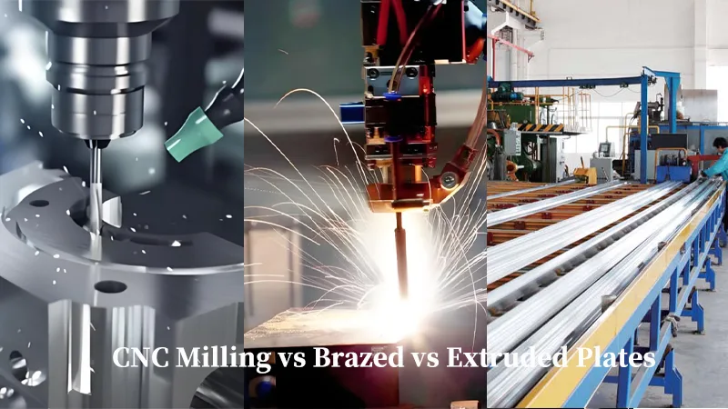
CNC milling excels in low-to-mid volume production where design flexibility matters. If your cooling plate design is still evolving, or if you need to produce multiple variants for different battery chemistries or pack configurations, CNC milling allows you to iterate without retooling. Lead time from design freeze to first article is typically 4–6 weeks, and design changes can be implemented with a CAM program update rather than mold or die rework.
The economic crossover point where brazing or stamping becomes cost-competitive is typically around 10,000–15,000 units per year, depending on part complexity and the cost of brazing tooling. Brazed plates are formed from stamped halves that are stacked and vacuum-brazed to create internal channels. The process is fast and scalable, with cycle times under 2 minutes per plate in high-volume production. The drawback is design lock-in—once the stamping dies are cut, changing channel geometry or port locations requires new tooling for $50,000–$150,000 per tool set.
Extruded cooling plates use aluminum extrusion to create long sections with integral internal channels, which are then cut to length and end-capped. Extrusion offers excellent material utilization and low unit cost at high volume, but it constrains your design to straight-channel geometries and limits port placement options. Extrusion is most cost-effective for simple, high-volume cooling plates with uniform cross-section along the length.
Your process selection should consider not just unit cost, but also tooling amortization, scrap risk during ramp, and the cost of design changes. If your product roadmap includes multiple pack sizes or cooling strategies, the flexibility of CNC milling may justify the higher unit cost through NRE avoidance and faster time to market.
Volume, Lead Time, and TCO Considerations
Lead time and volume are the dominant variables in process selection. For prototype builds and pre-production validation—typically 50–500 units—CNC milling is the only practical option. Tooling cost for brazing or stamping cannot be justified at this volume, and extrusion requires minimum order quantities that exceed your need.
In the 1,000–10,000 units per year range, CNC milling remains competitive if design changes are likely or if you value supplier flexibility and shorter lead times. At this volume, unit cost for a milled plate is typically $80–$200 depending on complexity and channel density, compared to $40–$100 for a brazed plate once tooling is amortized. The higher unit cost is offset by zero tooling NRE and the ability to run small batches without minimum order penalties.
Above 15,000 units per year, brazing or stamping dominates on unit cost, and lead time for repeat orders drops to 2–4 weeks once tooling is validated and in production. If your program is stable and you have confidence in the design, the lower unit cost and faster cycle time make brazing the economically rational choice.
Total cost of ownership must also account for scrap and rework. CNC milling has lower scrap risk because each part is individually machined and inspected. Brazing produces scrap in batches—if a furnace cycle fails, you may lose 20–50 parts at once. Factor this into your safety stock and cost model.
Risk Controls for OTD and Engineering Changes
On-time delivery (OTD) risk is managed through supplier capacity planning, buffer stock, and change control discipline. For CNC-milled cooling plates, the lead time driver is machining capacity, not material. Aluminum 6061-T6 plate stock is a commodity with short lead times, so the constraint is your supplier’s machine hours. Verify that your supplier has dedicated capacity or flexible scheduling to absorb demand spikes without extending lead time.
Engineering changes are a fact of life in new EV programs. A well-structured supplier relationship anticipates this and defines how changes will be handled. For CNC milling, most geometry changes can be implemented with a CAM update and dimensional verification—total lead time for a minor change is typically 1–2 weeks. For brazed or stamped plates, any change affecting the stamping die requires retooling, adding 8–12 weeks and high cost.
Your supplier agreement should define engineering change notification lead time, cost responsibility, and PPAP re-submission requirements. A minor change that does not affect special characteristics may require only a partial PPAP update, while a major change affecting form, fit, or function requires full re-PPAP. Negotiate these terms before PO placement to avoid disputes during ramp.
Conclusion
Purchasing and qualifying aluminum 6061-T6 liquid cooling plates for EV battery packs is a systems-level decision that requires understanding the interplay between thermal design, manufacturing process, quality controls, and total cost. The specifications and controls outlined in this guide are not theoretical—they are the minimum requirements to ensure that your supplier delivers parts that meet dimensional tolerances, leak integrity, and surface quality standards consistently over the life of your program.
Key CTQs to Include in Your RFQ and PO
When issuing an RFQ or PO for CNC-milled cooling plates, your specification package must include:
- Channel geometry tolerances: Width, depth, and positional accuracy sufficient to preserve CFD-validated hydraulic performance, typically ±0.05 mm for microchannels and ±0.1 mm for standard channels
- Flatness specification: Battery-contact surface flatness ≤0.05 mm for high-performance applications or ≤0.2 mm for standard applications, measured with the part free of clamping forces
- Sealing land requirements: Continuous flat sealing surface with specified width, flatness tolerance, and surface finish compatible with your gasket or O-ring design
- Surface finish targets: Ra ≤0.8 μm for coolant-wetted channels, Ra ≤1.6 μm for battery-contact face, Ra ≤3.2 μm for sealing lands
- Leak test method and acceptance limit: Helium mass spectrometry with defined test pressure and reject threshold, or pressure decay with validated correlation to helium results
- Material certification: Aluminum 6061-T6 with mill cert showing composition and mechanical properties
- Surface treatment specification: Anodizing type and thickness, or conversion coating type, with masking or post-coat machining instructions for critical surfaces
- Traceability requirements: Serial number or batch code linking each part to material lot, machining setup, inspection data, and leak test result
Testing and Compliance Checklist to Align Suppliers
Use this checklist during supplier selection and PPAP review to verify that the supplier can meet automotive quality standards:
- Control plan covers all special characteristics with defined inspection method, frequency, and reaction plan
- PFMEA addresses high-risk failure modes, including tool wear, fixturing error, contamination, and leak test equipment failure
- MSA studies demonstrate gage R&R <10% for all gages measuring special characteristics
- Capability studies show Cpk ≥1.33 for standard characteristics and Cpk ≥1.67 for special characteristics
- Leak test equipment calibrated with traceable standards and capable of measuring to the specified acceptance limit
- Cleaning validation report documents particle counts and residue removal effectiveness
- Material certs confirm 6061-T6 alloy and T6 temper with minimum mechanical properties
- IMDS submission complete and approved by customer
- First Article Inspection report includes measured values for all drawing dimensions with conformance statement
- Traceability system demonstrated by pulling full history for a sample serial number
When to Choose 6061-T6 Cooling Plates CNC Milling for EV Batteries
CNC milling of aluminum 6061-T6 is the right choice when your program values design flexibility, rapid iteration, and tight dimensional control over unit cost optimization. It is the preferred process for:
- Prototype and pre-production builds where design is still evolving, and tooling investment cannot be justified
- Low-to-mid volume production (under 10,000–15,000 units per year) where brazing or stamping tooling cost cannot be amortized
- Complex channel geometries including microchannels, serpentine layouts with tight bends, or multi-pass flow paths that are difficult or impossible to achieve with stamping
- Programs with multiple variants where producing 3–5 different cooling plate designs without retooling is a competitive advantage
- Applications requiring tight flatness and surface finish control where the dimensional precision of CNC machining justifies the cost premium
If your program is high-volume, design-stable, and cost-sensitive, investigate brazing or stamping alternatives once you have validated the design with CNC-milled PPAP parts. If your program is in the 1,000–10,000 unit range with ongoing design refinement, CNC milling offers the best balance of flexibility, lead time, and total cost.
The cooling plate is not a commodity. It is a precision component that determines whether your battery pack operates within thermal limits or suffers accelerated degradation and field failures. Invest the time to specify it correctly, qualify suppliers rigorously, and maintain process discipline through production. The cost of getting it right is far lower than the cost of getting it wrong.
FAQ
Why is aluminum 6061-T6 the standard material for CNC-milled EV battery cooling plates?
It comes down to balance. 6061-T6 holds a yield strength around 240–276 MPa while staying light, corrosion-resistant, and highly machinable, so shops can cut tight channels and sealing features without fighting the tool. Its thermal conductivity, roughly 167 W/m·K, is more than enough for most battery thermal loops, and it welds and anodizes cleanly. Compare that to copper, which transfers heat faster but costs several times more and adds weight, or cast alloys, which can hide internal voids that later become leaks. Unless your heat flux is extreme or space is severely constrained, 6061-T6 delivers the best combination of performance, weight, and landed cost—which is why it shows up across the majority of milled cold plate programs.
What flatness and leak-test limits should I put on my drawing?
For the battery-contact surface, specify flatness ≤0.05 mm on high-performance plates, or ≤0.2 mm where thicker thermal pads are used. For leak testing, helium mass spectrometry gives the tightest detection—commonly ≤10⁻⁸ mbar·L/s for water-glycol circuits—while pressure decay at ≤1 psi drop over 120 seconds at 30 psig is a practical production screen. The right limit should trace back to your coolant-loss budget over the warranty period, not a value copied from another program. Whichever method you choose, require the test pressure, dwell time, and per-serial traceability to be documented in the control plan and PPAP package.
Is CNC milling or vacuum brazing cheaper for EV cooling plates?
It depends on your volume and how stable your design is. CNC milling wins below roughly 10,000–15,000 units per year, because it needs no tooling investment and lets you change channel geometry with a CAM update instead of new dies. Brazed plates beat it on unit cost at high volume—cycle times can drop under 2 minutes—but you pay for stamping dies, often $50,000–$150,000 per set, and any geometry change forces retooling. If your program is still iterating or spans multiple pack variants, milling usually saves more through avoided NRE and faster time to market than the higher per-part price costs you.