
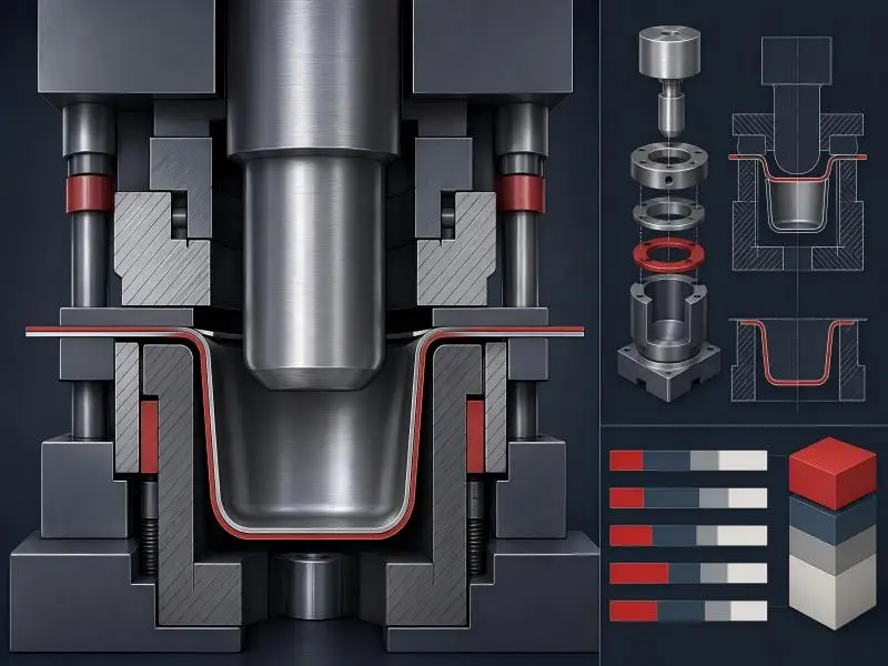
Custom deep drawing services make sense once a part’s annual volume clears roughly 5,000 units for cylindrical shapes, the point at which the standard volume break-even rules put deep drawing ahead of laser cutting and custom dies (DFMA). Below that threshold, simpler forming routes usually cost less, so the first question is not whether deep drawing is better in general but whether your volume and geometry fit it.
The economics can shift faster than most buyers expect. In a documented break-even case, a telecom aluminium shielding enclosure paid back its tooling in 14 months at 100,000 units per year and saved money after that, replacing four stamping operations plus manual assembly with one die and one operation (goldsupplier, 2026-07-27).
This guide covers the capability envelope (tolerances, draw ratios, materials, secondary operations), the cost and lead-time levers that drive total cost of ownership, and the quality documentation an OEM should expect, including PPAP Level 3 deliverables. It draws on published cost and tooling comparisons rather than vendor claims, and states where the public record is thin.
Key Takeaways
- Deep drawing typically becomes economical above about 5,000 units for cylindrical shapes, with progressive dies favored above 10,000 units (DFMA).
- A documented break-even case reached payback in 14 months at 100,000 units per year, consolidating four stamping operations and manual assembly into one die and one operation (goldsupplier, 2026-07-27)).
- Tooling investment can fall by around 30% when a stamping route converts to deep drawing, according to the same case set.
- Fit depends on geometry and volume first: stamping and machining stay competitive at low volumes or where wall thickness and features fall outside the deep drawing envelope.
AFI Industrial Co., Ltd. is a metal parts manufacturer headquartered in China with over 20 years of industry experience in custom metal parts production. Its in-house capabilities include metal stamping, sheet metal fabrication, and engineering support for design optimization, which are directly relevant to custom deep drawing work. The company has completed more than 200,000 custom projects for over 1,200 global clients, from rapid prototyping to mass production.
Table of Contents
Introduction
The first question to settle is volume. Custom deep drawing services become the economical route once a program passes roughly 5,000 units for cylindrical shapes, while laser cutting or a simple custom die holds the cost advantage below that threshold, according to the standard volume break-even rules published by DFMA. Above 10,000 units, a progressive die usually wins on unit cost. The decision is not whether deep drawing is a good process in the abstract, but where your part and your annual volume sit against those bands.
A documented break-even case shows how quickly the math can turn. A telecom aluminium shielding enclosure produced by deep drawing reached break-even in 14 months at 100,000 units per year and saved money thereafter, because one die and one operation replaced four stamping operations plus manual assembly (goldsupplier deep drawing vs stamping, 2026-07-27). The same source records a stainless-steel sink shell that cut total cost of ownership by 18% over a 50,000-unit annual volume against a multi-piece stamped-and-welded route.
This guide covers what to evaluate before you commit: capability limits on tolerances, draw ratios, materials and thickness; the cost levers that actually move at volume; lead time and scalability; and how deep drawing compares with stamping and machining. It also walks through the compliance path, including ISO 9001 and IATF expectations, PPAP Level 3 deliverables, and the control plan, MSA and FAI documents a launch team will ask for. The goal is a decision you can defend to engineering, procurement and quality at the same time.
Key Takeaways
- Deep drawing typically becomes economical above about 5,000 units for cylindrical shapes, with progressive dies favored above 10,000 units (DFMA).
- In one documented case, a deep-drawn telecom enclosure broke even in 14 months at 100,000 units per year by replacing four stamping operations and manual assembly with one die and one operation (goldsupplier, 2026-07-27).
- A stainless-steel sink shell saved 18% in total cost of ownership over a 50,000-unit annual volume versus a multi-piece stamped-and-welded route.
- Evaluate suppliers on tolerance and draw-ratio limits, material and thickness range, secondary operations, and PPAP readiness, not on unit price alone.
Custom Deep Drawing Capabilities
Custom deep drawing produces a seamless metal cup, shell, or enclosure from a flat blank in a single press cycle, and its practical limits are set by three things: how far the metal can be drawn before it tears, which material and thickness you specify, and how much secondary work remains after the part leaves the die. Each of those is a specification you can write into a purchase order, which is why the process fits an evaluation checklist better than a general capability claim.
A useful first distinction is what a supplier means by tolerance. A die-hold tolerance is what the tool itself can repeat once it is built and running, and it is the number that appears on a capability sheet. A process-hold tolerance accounts for material lot variation, lubrication, press condition, and springback across a production run. The two are not the same figure, and a quote that lists only the first one is not yet a commitment you can audit.
Key Takeaway: Ask every custom deep drawing services supplier to separate die-hold tolerance from process-hold tolerance. The die-hold number describes the tool; the process-hold number describes what you will actually receive across a production run, and only the second one belongs in your acceptance criteria.
Tolerances & Draw Ratios
Draw ratio math answers the question that decides your tooling budget: will this part run in one stage or several? The single-stage draw ratio ceiling, calculated as blank diameter divided by punch diameter, sits at 1.8 to 2.3 for a single draw, and ratios above 3.0 require multi-stage progressive drawing (Xometry, retrieved 2026-08-15). Published deep-drawing ratios by material narrow that band further: low-carbon steel runs about 1.8 to 2.0 on the first draw, stainless 304 and 316 about 1.6 to 1.8, and brass or copper about 1.8 to 2.2, with aluminium varying widely by alloy; subsequent draws typically fall to 1.2 to 1.4 (Balford, retrieved 2026-08-15).
A second, faster screen is the common depth-to-diameter working threshold of about 0.5 for a single draw (Balford, retrieved 2026-08-15). A cup 40 mm across and 18 mm deep sits comfortably inside that; the same diameter at 30 mm deep does not, and the quote should come back with a multi-stage tool plan.
| Part geometry | Single-draw screen | Likely tooling path |
|---|---|---|
| Depth-to-diameter under 0.5 | Inside the working threshold | Single-stage die |
| Ratio 1.8 to 2.3, shallow depth | Inside the single-stage LDR ceiling | Single-stage die, tight process window |
| Ratio above 3.0 | Beyond single-stage limits | Multi-stage progressive drawing |
Treat the ratio figures as engineering rules of thumb rather than measurements of your specific part. The material grade, temper, and blank-holder force all move the real ceiling, so the ratio gets you to the right conversation and the die trial settles it.
Materials & Thickness Ranges
Material choice sets both the achievable geometry and the tolerance you can hold. A supplier’s stated tolerance capability illustrates the range available: material thickness from 0.10 to 3.0 mm in sheet, strip up to 650 mm wide, with piloted progressive dies holding ±0.005 mm positional accuracy and mated features to ±0.01 to 0.02 mm (iStamping, retrieved 2026-08-15).
One supplier’s published capability envelope is narrower and more specific: draw ratios up to 2.0:1 on the first draw, blank diameters under 1 in up to 18 in, draw depths exceeding 10 in through multiple redraws, diameter tolerances of ±0.002 in on well-controlled draws, and wall thickness within ±0.005 in (Durex, retrieved 2026-08-15). Read those two side by side and the lesson is that capability statements are supplier-specific, not industry constants.
Two material behaviors matter when you write the drawing. First, wall thickness in a drawn part is a gradient rather than a single value: roughly 1.00 × nominal at the bottom centre, thinning to about 0.85 in the lower wall, and recovering to about 1.05 at the top edge (Balford, retrieved 2026-08-15). If your design assumes uniform wall, the lower wall is where it will fail. Second, die clearance per side is material-dependent: steel about 1.1 to 1.3 × material thickness, aluminium about 1.0 to 1.2 ×, and stainless about 1.2 to 1.4 × (Balford, retrieved 2026-08-15). Clearance drives both the tool build and the surface quality you get from it.
Pro Tip: When intermediate annealing becomes necessary, typically at 650 °C to 900 °C once a part exceeds the single-stage draw ratio limit, it is a real cost and lead-time line rather than a footnote (Xometry, retrieved 2026-08-15). Ask for it as a separate quote line instead of letting it disappear into a piece price.
Secondary Ops & Surface Finish
The honest answer to “how much secondary work remains after drawing” is that it depends on how early you involve the process in the design. DFMA’s cross-case cost breakdown, from Boothroyd Dewhurst, puts 72% of product cost in piece-part cost, 24% in overhead, and 4% in labor, and across more than 170 DFMA case studies the average part-count reduction was 54% (DFMA, updated 2026-07-08). That distribution is the argument for consolidating features into the drawn part: trimming, piercing, and forming operations performed in the die remove parts, fasteners, and assembly labor from the total rather than shifting them downstream.
In practice, secondary operations for deep drawn metal parts fall into three groups. In-die operations, such as trimming, piercing, and coining, add tooling cost but no separate handling step. Off-press operations, including deburring, machining of critical bores, and welding of sub-assemblies, add both handling and lead time. Surface finishing, whether plating, anodizing, powder coating, or passivation, is usually quoted separately and should be specified by the standard it must meet rather than by appearance alone.
Where the record stops: the DFMA figures are cross-industry averages drawn from a case-study library, not measurements of deep drawing specifically, and no independent test data isolating secondary-operation cost in deep drawing was found for this guide. Use the 72/24/4 split to frame the conversation with your supplier, and ask for a part-specific should-cost model before you treat any of it as a budget number.
TCO and Supply Chain Impact

Total cost of ownership for a deep drawn part is dominated by three levers: how the tooling cost is spread across volume, where your annual quantity sits relative to the break-even point against other processes, and how much working capital the lead time ties up. Purchase price per piece is the least useful number on its own, because two suppliers can quote the same unit price against very different tooling, scrap, and inspection loads.
Cost Levers at Volume
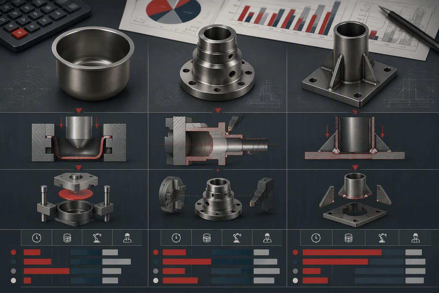
The first lever is amortization, and it is arithmetic rather than negotiation. DFMA’s sheet metal fabrication cost guidance sets out the standard tooling amortization formula as Unit Tooling Cost = Total Die Cost ÷ Production Volume. Run the numbers on a $20,000 die and the spread is stark: $20 per part at 1,000 units, $2 per part at 10,000 units, and $0.20 per part at 100,000 units. That single division explains most of the gap between a prototype quote and a production quote, and it is the number to put in front of procurement before anyone argues about piece price.
The second lever is process selection at your actual volume. The standard volume break-even rules place laser cutting and formed parts ahead of dedicated tooling somewhere around 2,000 to 5,000 units, deep drawing as economical above roughly 5,000 units for cylindrical parts, and progressive dies as the better route above 10,000 units. Brake bending stays cheapest below 1,000 units. These are planning bands, not promises: part geometry, material, and tolerance class move them.
The third lever is the one buyers usually miss, because it shows up in a different budget line. A documented break-even case for a telecom aluminium shielding enclosure reached break-even in 14 months at 100,000 units per year, replacing four stamping operations plus manual assembly with one die and one operation. In a separate stainless sink shell program, the switch produced an 18% TCO saving at 50,000 units per year alongside a 30% tooling cost reduction. The pattern is consistent: the savings come from collapsing operations and assembly labour, not from shaving cents off the blank.
Lead Time & Scalability
Tooling lead time, not press capacity, is what usually decides whether a supplier can hit your ramp. Typical die build lead times by die type run 25 to 30 days for single-station dies, 60 to 90 days for progressive dies, and 90 to 120 days for transfer dies. Deep drawing tooling trials add a further 10 to 20 days beyond tooling build, and CMM, first-article, PPAP, and FAI inspections add 3 to 10 days on top, with third-party inspection adding another 5 to 7 days. Those figures come from a 2026 supplier planning guide published by huaxiao-components, and they are planning estimates rather than guarantees.
Minimum order quantities follow the same complexity gradient. The same source puts deep drawing MOQs by complexity tier at 1,000 to 5,000 pieces for simple cylindrical cups, 3,000 to 10,000 for multi-draw parts, 5,000 to 20,000 for complex parts, and 100 to 500 pieces for prototypes run on 3D-printed or aluminium tooling. If your forecast sits below the tier your part geometry implies, the honest answer is usually a prototype tool first and a production tool once volume is committed.
Front-loading the drawing review compresses the calendar more reliably than chasing a faster press. AFI supports drawing review and DFM input ahead of tooling, which can be used to surface formability and tolerance conflicts before the die is cut. Note the limit on what this section can claim: no independent data was found on AFI’s PPAP or APQP launch support, so treat launch documentation as a question to put to any candidate supplier rather than an assumption.
Fit vs Stamping & Machining
Deep drawing vs stamping is not a contest between good and bad processes; it is a question of which one your geometry and volume reward. Stamping wins on flat and shallow parts, on volumes below the tooling break-even, and where design changes are still likely. Machining wins on low volumes, tight one-off tolerances, and parts where the geometry cannot be formed at all. Deep drawing wins when the part has real depth, when wall thickness must stay consistent, and when volume is high enough to amortize a die.
The decision matrix is short. Count the operations each route needs, including assembly. Check your annual volume against the break-even bands above. Then compare total cost per part, not piece price. The telecom enclosure case is instructive precisely because the win came from operation count: one die and one operation against four stamping operations plus manual assembly. If your part currently moves through three or four presses and a weld or rivet station, that is the signal to model deep drawing.
Where the record stops: the break-even figures above come from documented case examples rather than a controlled multi-part study, and no independent test data covering a broad range of geometries was found. Treat them as directional evidence and run the amortization arithmetic on your own part number before committing to tooling.
Quality and Compliance
Compliance evidence is a deliverable you specify in the purchase order, not a favor a supplier extends after the fact. For deep drawn metal parts, the useful question is not “are you certified” but “which standard applies to my program, and what documents will land in my inbox at each gate.” The three subsections below answer that in the order a launch actually happens: the standard and planning framework, the submission package, then the ongoing controls that keep the process honest after approval.
ISO 9001/IATF & APQP

ISO 9001 and IATF 16949 are not interchangeable, and the difference decides which suppliers can even quote your program. ISO 9001:2015 is the general quality management baseline, open to any manufacturer in any sector. IATF 16949 builds on ISO 9001 and adds automotive-specific requirements, so it applies to suppliers feeding automotive OEM programs and is the standard procurement teams screen for in that sector. If your end product is an industrial enclosure, medical device, or aerospace assembly, ISO 9001 plus the relevant sector standard (ISO 13485, AS9100D) is the correct screen, and demanding IATF 16949 from a non-automotive supplier narrows your vendor pool for no quality gain.
APQP is the planning framework that sits on top of whichever standard applies. The practical test of a supplier’s APQP discipline is timing: PPAP documentation is planned before tooling starts, reviewed with the customer while the die is still a drawing rather than assembled from records after the first parts come off the press. Ask when the PFMEA and control plan are drafted relative to the tooling PO. A supplier who answers “after we run samples” is telling you the launch will be reactive.
PPAP Level 3 Deliverables
PPAP Level 3 is the default submission level for most programs, and it is a document package, not a single certificate. The full Level 3 package includes design records and engineering change documents, customer engineering approval where required, DFMEA and PFMEA, the process flow diagram, a control plan covering critical and significant characteristics, MSA (GR&R) studies, dimensional layout results, material and performance test records, initial process studies with capability indices, qualified laboratory documentation, an appearance approval report where specified, sample production parts with master samples and checking aids, customer-specific requirements, and the signed PSW.
Two details trip up buyers. First, the 18 AIAG submission elements are numbered, and knowing the map helps you audit a package rather than trust it: DFMEA is element 4, PFMEA element 6, control plan element 7, MSA/GR&R element 8, initial process studies element 11, and the PSW element 18. If a supplier’s package skips element 11, the capability data is missing, not implied. Second, a common buyer misconception is that FAI belongs in the Level 3 submission. It does not. FAI is a continuing control performed at every new tool, transfer, or major process change, so treat it as a recurring checkpoint rather than a one-time line item.
Control Plan, MSA, and FAI
The control plan is only as good as the measurement system behind it, which is why MSA sits in the same package. A GR&R study tells you how much of your observed variation comes from the gauge and the operator rather than the part; a control plan built on an unqualified gauge measures noise.
Capability indices are where most buyers misread the data. Under the AIAG acceptance bands, an index above 1.67 meets requirements. Between 1.33 and 1.67 may be acceptable, but it requires customer agreement on disposition, typically enhanced controls, before submission. Below 1.33 does not meet requirements and triggers containment, corrective action with a timeline, and customer notification, with approval possible only as interim. Published 2026-07-05, that reference also settles the Ppk versus Cpk question: the initial study reports Ppk because it assumes no long-term stability, and Cpk applies only once stability is demonstrated.
Warning: Do not accept a Cpk figure on an initial submission. If the study reports Cpk before stability is proven, the supplier has either mislabeled the index or skipped the stability requirement. Ask for the Ppk value and the data behind it.
FAI closes the loop. Because it repeats at every new tool, transfer, or major process change, it is the control that catches drift after PPAP approval, and it is the document to request whenever your supplier changes a die, a press, or a material lot source.
Conclusion
Deep drawing earns its place in a supply chain when four signals line up: a seamless cylindrical or box-shaped geometry, a draw ratio the material can take in one or a few passes, wall thickness held across the full height, and an annual volume high enough to amortize tooling. When those signals are present, the process can replace multi-piece welded or machined assemblies with a single formed part, and the cost, lead time, and inspection burden shift accordingly. When they are not, stamping or machining usually wins.
Before you commit to tooling, run this validation sequence:
- Send a complete drawing package. Include tolerances, material specification, surface finish callouts, and annual volume. A supplier cannot confirm feasibility from a part outline alone.
- Ask for a DFM review against draw ratio limits. The supplier should state which passes are required and where the material is likely to thin or tear.
- Confirm the tooling timeline in writing. Ask for the build schedule and the first-article date, not a single lead-time figure.
- Match the PPAP level to your program. Confirm which level your customer requires and whether the supplier’s control plan, MSA, and FAI documentation meet it.
- Verify certification scope, not just the certificate. If your industry mandates IATF 16949 or AS9100D, confirm the scope covers your part and process before tooling starts, not after.
If you are weighing custom deep drawing services against stamping or machining for a specific part, request a DFM review and a tooling timeline. That single conversation resolves feasibility faster than any comparison table.
FAQ
What is the draw ratio in deep drawing, and what ratio can be achieved in one draw?
The draw ratio is the blank diameter divided by the punch diameter. A single draw typically handles a ratio of about 1.8 to 2.3, and anything higher needs multi-stage drawing, often with annealing between passes.
What tolerances can custom deep drawing services hold?
Published capability ranges vary by supplier and material, but ±0.05 mm on critical features and around ±0.1 mm as a typical figure are common. Tighter limits depend on material, wall thickness, and the number of drawing stages.
What is the minimum order quantity for deep-drawn parts?
Because deep drawing needs dedicated tooling, most suppliers set the practical floor at a few hundred pieces, with common MOQs of 1,000 to 10,000 depending on part complexity. Prototypes often run from 50 pieces on softer tooling.
How does deep drawing compare with stamping and machining?
Deep drawing suits deep, hollow, seamless parts at volume; stamping suits flat or shallow parts at high speed; and machining suits low-volume parts with complex features. The deep drawing crossover where it beats machining usually falls near 3,000 to 5,000 units.